◆ Technical Parameters:
|
Model
|
CYB100
|
CYB150
|
|
Nominal diameter
|
Φ100
|
Φ150
|
|
Mounting type
|
Radial convex mounted
Parallel interfaces
|
*
|
*
|
|
Radial convex mounted
Eight-character interface
|
/
|
*
|
|
Eccentric eccentric flush type
|
/
|
*
|
|
Measuring range
|
Differential pressure
Measuring range
KPa
|
Nominal
Work pressure
KPa
|
Differential pressure
Measuring range
MPa
|
Nominal
Work pressure
MPa
|
|
0~10
|
60
|
0~0.16
|
1
|
|
0~16
|
100
|
0~0.25
|
1.6
|
|
0~25
|
160
|
0~0.4
|
2.5
|
|
0~40
|
250
|
0~0.6
|
4
|
|
0~60
|
400
|
0~1
|
6
|
|
0~100
|
600
|
0~1.6
|
10
|
|
|
|
0~2.5
|
10
|
|
Accuracy class
|
2.5
|
|
Fitting threads
|
M20×1.5
|
|
Use ambient temperature
|
-40℃~70℃
|
|
The temperature of the medium to be used
|
≤60℃
|
|
Vibration resistance rating
|
V· H· 3
|
|
Enclosure rating
|
IP54
|
|
weight
|
Approximately 1.0 kg
|
|
Material of the impulse system
|
0Cr17Ni12Mo2、SUS316
|
|
casing and other materials
|
1Cr18Ni9、SUS304
|
|
Enforce the standard
|
JB/T 12015-2014
|
|
Note: 1. The joint thread can be customized according to user requirements.
|
◆ Appearance and installation size:
|

CYB100 Parallel Interface
|

CYB150 Parallel Interface
|
|

CYB150 Bazi interface
|
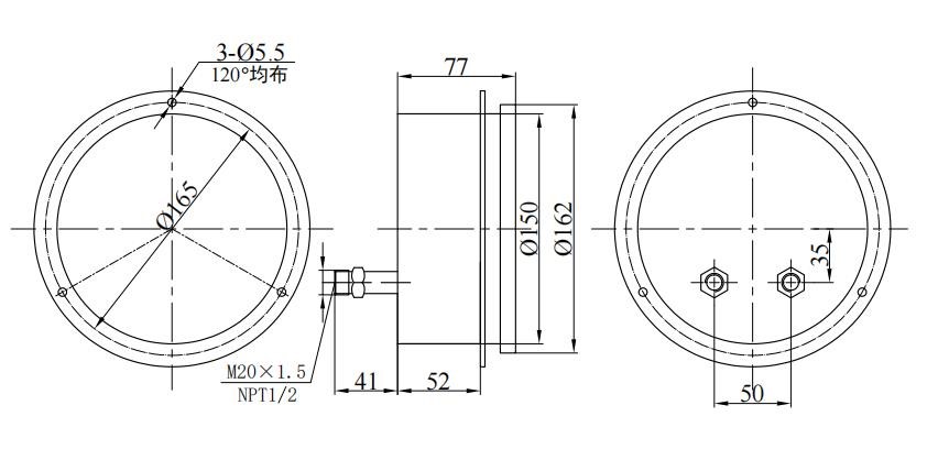
CYB150 axial eccentricity
|
◆ Structural principle:
The instrument adopts a double Bourdon tube structure, that is, two Bourdon tubes are installed in symmetrical positions on both sides of the "I" bracket. The upper and lower sections of the "I" bracket are the movable end and the fixed end respectively, and the middle is connected by a spring piece: the two Bourdon tubes are in a parallel state, and are connected with the high and low voltage joints on the case with the conduit respectively: the gear transmission mechanism is directly installed at the fixed end of the bracket, and is connected with the movable end of the bracket through the pull rod: the dial is directly fixed on the gear transmission mechanism.
◆ Working principle: Based on the pressure sensing element, two Bourdon tubes with the same stiffness are used, so they are forced to produce the same concentrated force under the same measured medium to act on the movable bracket respectively, because the two sides of the spring blade do not produce deflection under the action of equal moment, so the bracket is still in the original position, so that the gear transmission mechanism does not act, so that the pointer is still pointed at the zero position.
When different pressures are applied (generally the high-pressure end is higher than the low-pressure end), the force of the two Bourdon tubes acting on the movable support is not equal, so that the corresponding displacement is generated respectively, and the gear transmission mechanism is driven and amplified, and the differential pressure value between the two is indicated after the pointer is deflected.
◆ Precautions:
1. The instrument should be installed vertically at a position that is at the same level as the measuring point, otherwise the additional error caused by the liquid level difference must be taken into account.
2. The instrument connector marked with "H" or "+" is the high-voltage end, and the one marked with "L" or "-" is the low-voltage end, which cannot be reversed during installation.
3. When the instrument measures the differential pressure, the differential pressure value can be used within 75% of the upper limit of the scale range, and the maximum static pressure value of the system should not exceed the maximum static pressure value specified by the instrument.
4. As shown in Figure 4, the balance (safety) valve (valve 1) should be set in front of the high and low pressure input ports of the instrument during installation, and should be in the open position, and the balance valve should be closed after the valve 2 and valve 3 are all opened.
5. Before use, the instrument should carefully verify the degree of erosion caused by the measured medium, so as not to cause early corrosion damage to the Bourdon tube.
◆ Ordering Instructions:
When ordering the instrument, the user must indicate:
1. Model and name, differential pressure range, maximum static pressure, unit of measurement, accuracy level;
2. Fitting and Bourdon tube material;
3. Joint thread size: conventional M20×1.5, NPT1/2 (or customer's designation);
4. Note: Three valve groups can be customized on behalf of users (valves 1~3 in Figure 4)


 English
 русский
 Español
 عربى
عربى