
 English
 русский
 Español
 عربى
عربى
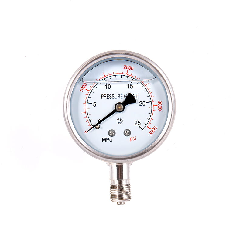
YN series 100% copper connection earthquake-resistant (seismic) pressure gauge
Cat:Pressure Gauge
◆ Model: YN40 YN50 YN60 YN75 YN100 YN150◆ Use: This series of instruments have good shock resistance...
See DetailsContent
Pressure gauges are essential instruments used across countless industries to measure and display the pressure of gases or liquids within a system. These devices serve critical functions in monitoring system performance, ensuring safety, preventing equipment damage, and maintaining optimal operating conditions. From the simple tire pressure gauge in your garage to sophisticated digital instruments in nuclear power plants, pressure measurement devices come in numerous configurations, each designed for specific applications, pressure ranges, and environmental conditions.
The fundamental purpose of any pressure gauge is to convert pressure force into a readable measurement that operators can monitor and act upon. This conversion happens through various mechanical, electrical, or electronic mechanisms depending on the gauge type. Understanding the different categories of pressure gauges, their operating principles, advantages, limitations, and ideal applications enables engineers, technicians, and facility managers to select the most appropriate instrument for their specific requirements. Proper gauge selection directly impacts measurement accuracy, system safety, maintenance costs, and operational efficiency.
Mechanical pressure gauges represent the most traditional and widely-used category of pressure measurement devices. These instruments use physical deformation of elastic elements to indicate pressure, requiring no external power source and offering reliable performance in diverse environments. Their simplicity, durability, and cost-effectiveness make them the default choice for many industrial applications.
The Bourdon tube gauge stands as the most common mechanical pressure measuring device, invented by Eugène Bourdon in 1849 and still dominating industrial applications today. This gauge employs a curved, flattened tube with an oval cross-section, sealed at one end and connected to the pressure source at the other. When pressure enters the tube, it attempts to straighten, causing the sealed end to move. This movement transfers through a mechanical linkage system consisting of gears and levers that rotate a pointer across a calibrated dial, providing a visual pressure reading.
Bourdon tubes come in three primary configurations: C-type (most common, shaped like the letter C covering approximately 250 degrees), spiral (multiple turns for increased sensitivity and range), and helical (similar to spiral but with coils arranged vertically). C-type Bourdon tubes typically measure pressures from 12 psi to 100,000 psi, making them suitable for most industrial applications including hydraulic systems, pneumatic equipment, compressors, and process monitoring. The spiral and helical configurations provide greater pointer movement for the same pressure change, improving readability for low-pressure applications or when high accuracy is required.
Diaphragm pressure gauges utilize a flexible circular membrane that deflects in response to pressure differences between its two sides. One side typically experiences the process pressure while the other remains at atmospheric pressure or a reference pressure. The diaphragm's deflection transfers to a pointer mechanism through mechanical linkages, similar to Bourdon tube gauges. These instruments excel in measuring low pressures, typically from 0.5 inches of water column up to approximately 400 psi, where Bourdon tubes become less sensitive and accurate.
The primary advantage of diaphragm gauges lies in their ability to isolate the pressure-sensing element from the process medium. This isolation proves invaluable when measuring corrosive, viscous, contaminated, or high-temperature fluids that would damage or clog other gauge types. Diaphragm materials range from stainless steel and exotic alloys for chemical resistance to elastomers like PTFE or rubber for flexibility. The diaphragm can be sealed with fill fluid and connected to a standard Bourdon tube movement, creating a chemical seal system that combines the benefits of both technologies.
Capsule gauges consist of two diaphragms joined at their periphery, creating a sealed cavity that expands or contracts with pressure changes. This design offers enhanced sensitivity compared to single diaphragms, making capsule gauges ideal for very low pressure or differential pressure measurements, typically in ranges from 0.25 inches of water column to 30 psi. Bellows gauges use accordion-like metallic tubes that expand and contract axially in response to pressure. The bellows design provides significant linear displacement, allowing direct connection to pointer mechanisms without complex linkages. These gauges typically measure pressures from 1 psi to 600 psi and find applications in pneumatic control systems, draft measurement, and low-pressure gas applications.
Electronic pressure gauges convert pressure into electrical signals that can be displayed digitally, transmitted to control systems, or recorded for analysis. These sophisticated instruments offer advantages including higher accuracy, remote monitoring capabilities, data logging, programmable alarms, and integration with automated control systems. While more expensive than mechanical gauges, digital instruments provide functionality that justifies their cost in applications requiring precision, documentation, or remote access.
Strain gauge transducers represent the most common electronic pressure measurement technology. These devices bond resistive strain gauges to a flexible diaphragm or other pressure-sensitive element. When pressure causes the diaphragm to flex, the strain gauges experience mechanical deformation that changes their electrical resistance. Typically arranged in a Wheatstone bridge configuration, these resistance changes generate a small voltage output proportional to applied pressure. Signal conditioning circuits amplify and linearize this voltage, converting it to standard output signals like 4-20 mA current loops or 0-10 VDC for transmission to display units or control systems.
Modern strain gauge transducers achieve accuracies of 0.25% to 0.05% of full scale, significantly exceeding mechanical gauge capabilities. They measure pressures from fractions of a psi to over 100,000 psi across various designs. Their compact size, fast response time, and electrical output make them ideal for dynamic pressure measurement, automated process control, test and measurement applications, and anywhere data logging or remote monitoring is required.
Capacitive pressure sensors measure pressure by detecting changes in capacitance as a diaphragm moves relative to a fixed electrode. Pressure causes the sensing diaphragm to deflect, altering the gap between capacitor plates and thus changing the capacitance value. Electronic circuits measure this capacitance change and convert it to a pressure reading. Capacitive sensors offer exceptional sensitivity and stability, making them suitable for precise low-pressure measurements and applications requiring long-term stability with minimal drift. They excel in clean, dry gas applications but may require more complex signal conditioning compared to strain gauge devices.
Piezoelectric sensors utilize crystals that generate electrical charge when subjected to mechanical stress. Applied pressure creates stress in the crystal, producing a charge proportional to the pressure magnitude. These sensors respond extremely quickly to pressure changes, making them ideal for dynamic pressure measurement applications such as engine testing, ballistics, blast pressure measurement, and high-frequency vibration monitoring. However, piezoelectric sensors cannot measure static or slowly changing pressures since the generated charge gradually leaks away. They serve specialized applications where their unique capabilities justify their higher cost and limited pressure range.
Beyond standard mechanical and electronic gauges, several specialized pressure measurement devices serve specific industries or unique measurement requirements. Understanding these specialized categories helps identify optimal solutions for challenging applications.
| Gauge Type | Pressure Range | Typical Applications |
| Differential Pressure Gauges | 0-0.5 to 0-1000 psi difference | Filter monitoring, flow measurement, HVAC systems |
| Absolute Pressure Gauges | 0-30 psia to 0-10,000 psia | Vacuum systems, altitude compensation, barometric measurement |
| Vacuum Gauges | 760 Torr to 10⁻⁹ Torr | Vacuum chambers, analytical instruments, semiconductor manufacturing |
| Sanitary Pressure Gauges | 0-30 to 0-3000 psi | Food processing, pharmaceutical, biotechnology |
| Test Gauges | Varies (high accuracy) | Calibration, precision testing, reference standards |
| Digital Display Gauges | Full range capability | Retrofit applications, improved readability, data logging |
Differential pressure gauges measure the pressure difference between two points in a system rather than absolute pressure. These instruments feature two pressure ports, comparing the pressures and displaying only the difference. Applications include filter condition monitoring (measuring pressure drop across filters to indicate clogging), flow measurement using restriction devices like orifice plates, level measurement in sealed tanks, and HVAC system balancing. Differential gauges use various sensing elements including dual diaphragms, opposed bellows, or dual Bourdon tubes, depending on the pressure range and application requirements.
Industries like food processing, pharmaceuticals, and biotechnology require pressure gauges designed for easy cleaning and sterilization. Sanitary pressure gauges feature smooth, crevice-free wetted surfaces, typically with tri-clamp or other sanitary process connections. Materials meet FDA requirements, with 316L stainless steel being standard. Diaphragm seals isolate the sensing element from the process, allowing steam sterilization or clean-in-place (CIP) procedures without damaging the gauge mechanism. These specialized instruments cost more than standard gauges but provide essential sanitation capabilities for regulated industries.
Understanding pressure measurement reference points is crucial for proper gauge selection and application. Pressure can be expressed relative to different reference points, and selecting the wrong reference type causes measurement errors or equipment malfunction.
Selecting the appropriate pressure gauge requires evaluating multiple factors beyond just the pressure range. Poor gauge selection leads to inaccurate readings, premature failure, safety hazards, or unnecessary expense. A systematic selection process considers all relevant application parameters to identify the optimal instrument.
Gauge pressure range should extend to approximately 150-200% of normal operating pressure to prevent damage from pressure spikes while maintaining good readability. Operating continuously near a gauge's maximum range causes excessive wear and reduces accuracy. For critical applications, consider installing both a process gauge for continuous monitoring and a test gauge for periodic precision verification. Accuracy specifications vary widely, from ±3% for general purpose gauges to ±0.25% or better for precision test instruments. Balance accuracy requirements against cost, as precision gauges cost significantly more than standard industrial gauges.
The pressure gauge's wetted materials must resist corrosion or degradation from the process medium. Standard brass or bronze internals suit water, air, and non-corrosive fluids. Stainless steel construction handles mildly corrosive applications. Exotic alloys like Hastelloy or Monel serve highly corrosive environments. For extreme chemical compatibility challenges, consider diaphragm seals with appropriate seal materials isolating the gauge from the process. Environmental factors including temperature, vibration, humidity, and hazardous area classification also influence selection. Temperature extremes may require case fill fluid, heat dissipation accessories, or electronic gauges with remote sensors. Vibration-prone installations benefit from liquid-filled cases that dampen pointer movement and reduce wear.
Gauge dial size affects readability and cost. Common sizes include 2.5, 3.5, 4.5, and 6 inches, with larger dials providing easier reading from a distance but costing more and requiring more space. Mounting configurations include bottom mount (center back connection), back mount (upper back connection), panel mount, or surface mount with U-clamp. Process connections vary from 1/8 NPT to 1 inch NPT or larger, with pipe threads, flanged connections, or sanitary fittings depending on application requirements. Select connection size and type to match existing system plumbing while considering pressure drop and installation convenience.
Proper installation significantly impacts gauge performance, accuracy, and service life. Many pressure gauge failures result from installation errors rather than inherent instrument defects. Following established best practices prevents common problems and ensures reliable measurement.
Always install gauges with shutoff valves or gauge cocks that allow isolation for inspection, testing, or replacement without depressurizing the entire system. This simple addition greatly simplifies maintenance and reduces downtime. For pulsating pressure applications such as reciprocating pumps or compressors, install pulsation dampeners or snubbers to protect the gauge mechanism from rapid pressure fluctuations that cause premature wear and failure. Liquid-filled gauges provide internal dampening but cannot handle severe pulsation alone.
Position gauges at appropriate heights for easy viewing by operators while protecting them from physical damage. Avoid installations where gauges might experience impact, water spray, or extreme temperatures. For steam service or other high-temperature applications, install pigtail siphons or cooling towers to reduce temperature at the gauge connection to acceptable levels, typically below 200°F for standard gauges. Never install gauges directly in high-temperature lines without thermal protection, as heat damages the mechanism and voids warranties.
Pressure gauges require periodic maintenance and calibration to ensure continued accuracy and reliability. Mechanical gauges gradually lose accuracy due to wear, material fatigue, and environmental exposure. Electronic gauges experience drift, particularly strain gauge types, though typically at slower rates than mechanical instruments.
Establish calibration intervals based on application criticality, manufacturer recommendations, and historical performance data. General industrial applications often use annual calibration cycles, while precision or safety-critical applications may require quarterly or monthly verification. Maintain calibration records documenting gauge identification, calibration date, as-found condition, adjustments made, and as-left accuracy. These records satisfy quality system requirements and help identify gauges requiring more frequent calibration or replacement.
Simple visual inspections catch many problems before they cause measurement errors or safety issues. Regularly check for pointer movement when pressure changes, verify zero reading when depressurized, inspect for case damage or lens fogging, and look for leaks at connections. Replace gauges showing bent pointers, cracked crystals, corroded cases, or readings that don't return to zero. Many organizations establish maximum-use periods for critical gauges, replacing them automatically regardless of apparent condition to prevent age-related failures.
Pressure measurement technology continues evolving, with several trends shaping future instrument development and deployment. Wireless pressure sensors increasingly replace wired installations, particularly for remote or difficult-to-access locations. These battery-powered devices transmit readings via industrial wireless protocols, eliminating wiring costs while enabling pressure monitoring in previously impractical locations. Energy harvesting technologies promise to eliminate even battery maintenance requirements by generating power from vibration, temperature differentials, or solar radiation.
Smart pressure transmitters with advanced diagnostics, self-calibration capabilities, and predictive maintenance features represent another significant trend. These instruments monitor their own performance, detecting degradation before it affects measurement accuracy and alerting maintenance personnel to needed service. Integration with Industrial Internet of Things (IIoT) platforms enables cloud-based analytics, remote monitoring from anywhere, and incorporation of pressure data into comprehensive process optimization strategies. Despite these technological advances, traditional mechanical gauges will remain relevant for applications valuing simplicity, reliability without power requirements, and visual indication that operators can verify at a glance.
 pressure gauge")
◆ Model: YN40 YN50 YN60 YN75 YN100 YN150◆ Use: This series of instruments have good shock resistance...
See Details
◆ Model: YP100-L YP150-L YP100-F YP150-F ◆ Application: YP series instrument diaphragm and structura...
See Details
◆ Model: YD40 YD50 YD60 YD75 YD100 YD150 ◆ The main body of the instrument is a general pressure gau...
See Details
◆ Model: CYB100 CYB150 ◆ Application: Stainless steel differential pressure gauges is suitable for m...
See Details
◆ Model: YXC60 YX100 YXC-150 ◆ Application: Magnetic-assisted electric contact pressure gauges is su...
See Details
◆ Model: YTX100B YTX150B ◆ Uses: Explosion-proof electric contact pressure gauge is specially used i...
See Details
1. Overview This pressure transmitter has high sensitivity, high precision and strong anti-overload ...
See Details
◆ Model: YSZC-8 ◆ Application: This instrument is suitable for precise measurement of liquid level d...
See Details
◆ Model: WSSXCh-4, WSSXCh-5 ◆ Application: This series of thermometers has the characteristics of no...
See Details
The Valve remote control and liquid level telemetry system enhances operational efficiency by provid...
See Details


