
 English
 русский
 Español
 عربى
عربى
YQ series safety pressure gauge
Cat:Pressure Gauge
◆ Model: YQ40 YQ50 YQ60 YQ75 YQ100 YQ150◆ Use: This series of gauges are all made of stainless steel...
See DetailsContent
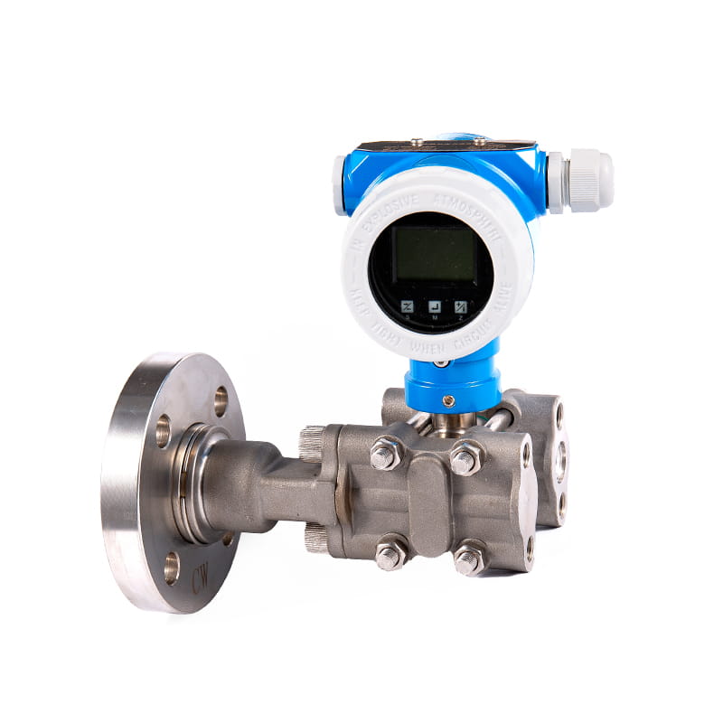
Differential pressure transmitters stand as essential instruments in modern industrial process control, measurement, and monitoring systems. These devices measure the difference in pressure between two points in a system and convert this measurement into a standardized output signal that control systems can interpret and act upon. For engineers, technicians, and plant operators new to instrumentation, understanding differential pressure transmitters opens the door to comprehending flow measurement, level detection, filter monitoring, and numerous other critical process applications. This comprehensive guide breaks down the fundamentals of differential pressure transmitters, explaining their operating principles, common applications, selection criteria, and practical implementation considerations in accessible terms that build a solid foundation for working with these versatile instruments.
At its core, a differential pressure transmitter measures the pressure difference between two input ports, typically labeled "high side" and "low side" or "positive" and "negative." The transmitter contains a sensing element that responds to this pressure differential, generating a proportional output signal regardless of the absolute pressure at either port. This differential measurement capability distinguishes these transmitters from gauge or absolute pressure transmitters that measure pressure relative to atmospheric pressure or a perfect vacuum respectively.
The sensing element in most modern differential pressure transmitters consists of a flexible diaphragm positioned between two pressure chambers. When different pressures apply to each side of this diaphragm, it deflects toward the lower pressure side. The amount of deflection corresponds directly to the magnitude of the pressure difference. Traditional designs used mechanical linkages to convert diaphragm movement into an output signal, but contemporary transmitters employ electronic sensing technologies that offer superior accuracy, stability, and reliability.
Capacitive sensing technology dominates modern differential pressure transmitter designs. In these devices, the diaphragm forms one plate of a capacitor, while fixed plates on either side complete the capacitive circuit. As the diaphragm deflects under differential pressure, the capacitance changes proportionally. Electronic circuitry measures these capacitance variations with extreme precision and converts them into standardized output signals such as 4-20 mA current loops or digital protocols like HART, FOUNDATION Fieldbus, or Profibus. This electronic conversion eliminates mechanical wear points and enables advanced features including digital communication, self-diagnostics, and remote configuration.
The output signal scaling allows users to configure the transmitter's response to match specific application requirements. A transmitter might be calibrated so that zero differential pressure produces a 4 mA output while the maximum rated differential produces 20 mA, with the output varying linearly across this range. This standardized signaling enables seamless integration with control systems, data acquisition equipment, and monitoring displays regardless of manufacturer or specific pressure range, creating interoperability across industrial automation ecosystems.
Differential pressure transmitters serve remarkably diverse applications across industries, making them among the most widely deployed process instruments. Understanding these common applications helps clarify why differential pressure measurement proves so valuable and guides appropriate transmitter selection for specific needs.
Flow measurement represents perhaps the most prevalent application for differential pressure transmitters. When a fluid flows through a restriction such as an orifice plate, venturi tube, or flow nozzle, the velocity increases at the restriction point while pressure decreases according to Bernoulli's principle. The pressure difference between the upstream and downstream measurement points relates mathematically to the flow rate. A differential pressure transmitter measuring this pressure drop enables accurate flow rate calculation for liquids, gases, and steam. This flow measurement principle has served industry for over a century, refined through extensive standardization and proven in countless installations across every industrial sector.
Level measurement in tanks and vessels employs differential pressure transmitters by measuring the hydrostatic pressure exerted by the liquid column. Installing the transmitter with its high side connected to the bottom of the tank and the low side vented to atmosphere or connected to the tank vapor space allows the transmitter to measure the pressure created by the liquid height. Since pressure equals liquid density multiplied by height and gravitational constant, the differential pressure reading directly indicates liquid level. This method works reliably for open and closed tanks, handles challenging process conditions, and requires no moving parts in contact with the process fluid.
Filter and strainer monitoring utilizes differential pressure measurement to indicate when cleaning or replacement becomes necessary. As particulate matter accumulates on filter media, flow resistance increases, creating a larger pressure drop across the filter. A differential pressure transmitter measuring upstream and downstream pressure provides continuous monitoring of this pressure drop. When the differential reaches a predetermined threshold, it signals that the filter requires servicing. This application prevents equipment damage from inadequate filtration while avoiding premature filter replacement, optimizing both protection and operating costs.
Selecting an appropriate differential pressure transmitter requires evaluating multiple technical specifications against application requirements. Understanding these specifications and their practical implications ensures you choose a transmitter that delivers accurate, reliable measurements throughout its service life while avoiding over-specification that unnecessarily increases costs.
The pressure range specification defines the minimum and maximum differential pressure the transmitter can measure accurately. Manufacturers offer transmitters with ranges from fractions of an inch of water column for low-pressure applications like draft measurement to hundreds or thousands of PSI for high-pressure processes. Proper range selection balances several factors: the range should encompass your maximum expected differential pressure with some margin for process upsets, but selecting too wide a range reduces measurement resolution and accuracy at typical operating conditions. As a general guideline, normal operating differential pressure should fall between 25% and 75% of the transmitter's calibrated span for optimal performance.
Accuracy specifications indicate how closely the transmitter's output corresponds to the actual differential pressure. Manufacturers express accuracy in various ways including percentage of span, percentage of reading, or absolute units. A transmitter with ±0.1% of span accuracy measuring a 0-100 inch water column range could deviate by ±0.1 inches from the true value anywhere across its range. Understanding whether accuracy specifications include the effects of temperature, static pressure, and long-term drift proves crucial, as these factors can significantly impact real-world performance beyond the laboratory calibration accuracy.
Wetted materials—the materials in direct contact with the process fluid—require careful consideration based on process chemistry, temperature, and pressure. The diaphragm and pressure sensor body must resist corrosion, erosion, and chemical attack from the measured fluid. Common diaphragm materials include 316 stainless steel for general service, Hastelloy for corrosive applications, tantalum for extremely aggressive chemicals, and various coatings or platings for specific compatibility needs. The process connection material and gaskets must similarly withstand process conditions throughout the transmitter's intended service life.
| Specification | Typical Range | Selection Consideration |
| Differential Range | 0.5 inH2O to 10,000 PSI | Match to maximum expected differential |
| Accuracy | ±0.04% to ±0.5% of span | Based on process control requirements |
| Static Pressure Rating | 150 PSI to 10,000 PSI | Must exceed maximum line pressure |
| Temperature Range | -40°F to 250°F ambient | Account for installation environment |
| Output Signal | 4-20mA, HART, Fieldbus | Match to control system interface |
Proper installation critically impacts differential pressure transmitter performance, with installation errors accounting for the majority of measurement problems encountered in industrial applications. Following established best practices ensures accurate, reliable measurements while avoiding common pitfalls that compromise performance or damage equipment.
Location selection represents the first installation decision, with multiple factors influencing optimal placement. The transmitter should mount as close to the pressure tap points as practical to minimize impulse line length, reducing response time and minimizing the volume of potentially hazardous process fluid outside the primary containment. However, mounting location must also provide adequate access for maintenance, protection from physical damage, and appropriate ambient temperature conditions. For outdoor installations, weather protection through enclosures or weather shields prevents moisture ingress and extreme temperature effects that could damage electronics or affect calibration.
Impulse line installation requires careful attention to prevent measurement errors from trapped gases, condensate accumulation, or sediment buildup. For liquid service, impulse lines should slope continuously upward from the process connection to the transmitter, preventing gas pockets from forming that would cushion the pressure transmission and create errors. Conversely, gas and steam service requires downward sloping lines that prevent liquid accumulation. The slope should be at least 1 inch per foot of horizontal run. Sharp bends and low points in impulse lines create potential trap points for contaminants and should be avoided through proper routing and support.
Manifold valves simplify transmitter maintenance and calibration by allowing isolation of the transmitter from the process and equalization of pressure across both sides of the sensing element. A three-valve manifold provides independent isolation of the high and low pressure inputs plus an equalizing valve that connects the two sides. This configuration enables safe transmitter removal for calibration or replacement without depressurizing the process. Five-valve manifolds add vent and drain valves for additional functionality. Proper valve operation sequences prevent overpressure damage during startup and shutdown procedures.
Electrical installation encompasses both power supply connections and output signal wiring. Most transmitters operate on 24 VDC power, either externally supplied or derived from the control system through the 4-20 mA current loop. Wire sizing must account for the total loop resistance to ensure adequate voltage remains available at the transmitter after accounting for voltage drops in the wiring. Shielded twisted-pair cable provides noise immunity for the low-level signals, with the shield grounded at a single point (typically the control system end) to prevent ground loops. Conduit seals prevent moisture migration into electronics enclosures in humid or wet environments.
Maintaining measurement accuracy throughout a transmitter's service life requires periodic calibration and preventive maintenance activities. Understanding calibration principles and establishing appropriate maintenance intervals ensures continued reliable performance while avoiding unnecessary downtime or excessive maintenance costs.
Calibration verifies that the transmitter's output signal accurately corresponds to the applied differential pressure input across the instrument's entire measurement range. The process involves applying known, traceable pressure inputs using calibration equipment and comparing the transmitter output to expected values. Modern digital transmitters often include internal diagnostics that can identify sensor drift or failure before calibration errors become significant, enabling condition-based maintenance rather than fixed calendar-based calibration schedules. However, regulatory requirements in some industries mandate periodic calibration regardless of diagnostic results.
Zero and span adjustments correct minor calibration deviations without requiring complete transmitter recalibration. The zero adjustment compensates for offset errors, ensuring the transmitter outputs 4 mA when no differential pressure exists. Span adjustment corrects gain errors, ensuring full-scale differential pressure produces the correct 20 mA output. Many modern transmitters allow these adjustments through digital communication protocols without requiring disconnection from the process, simplifying routine maintenance and reducing calibration labor costs.
Preventive maintenance beyond calibration includes regular inspection of impulse lines, fittings, and valve manifolds for leaks, corrosion, or blockage. Impulse line flushing removes accumulated sediment or scale that could affect pressure transmission accuracy. Diaphragm seal inspection identifies damage or degradation before failure occurs. Electrical connection inspection prevents intermittent failures from corroded terminals or loose connections. Recording maintenance activities and calibration results creates a performance history that can identify developing problems and guide predictive maintenance strategies.
Even properly selected and installed differential pressure transmitters occasionally develop problems requiring systematic troubleshooting to identify and correct root causes. Recognizing common failure modes and their symptoms enables faster diagnosis and resolution, minimizing process downtime and maintaining measurement integrity.
Erratic or noisy output signals often indicate problems with impulse lines rather than transmitter failure. Air bubbles in liquid-filled impulse lines cause varying pressure transmission as bubbles compress and expand with pressure fluctuations. Partially plugged impulse lines create similar symptoms as flow restriction varies with pressure changes. Both issues typically resolve through impulse line venting, draining, or flushing procedures. If output noise persists after clearing impulse lines, electrical interference from nearby power cables, motors, or variable frequency drives may couple into signal wiring. Verifying proper shielding and grounding or rerouting signal cables away from noise sources usually eliminates this problem.
Transmitters reading higher or lower than actual differential pressure despite recent calibration suggest installation issues affecting the measurement. For level applications, incorrect transmitter mounting elevation relative to the process connection creates an offset error proportional to the elevation difference and the impulse line fill fluid density. Temperature differences between the two impulse lines in high-accuracy applications can create density variations that appear as differential pressure errors. Condensation or vaporization in impulse lines similarly creates measurement errors by changing the effective pressure transmission path.
Complete signal loss or fixed output values point toward electrical or electronic failures. Verify power supply voltage at the transmitter terminals meets specifications, as insufficient voltage prevents proper operation. Check for open circuits in signal wiring, particularly at terminal connections where vibration can loosen screws over time. Modern smart transmitters provide detailed diagnostic information through digital communication protocols, identifying specific internal failures such as sensor malfunction, memory errors, or electronics problems that guide repair or replacement decisions. Keeping spare transmitters or critical replacement parts on hand minimizes downtime when component failures occur in critical measurement loops.
Understanding differential pressure transmitters equips you with knowledge essential for numerous industrial measurement applications. These versatile instruments deliver accurate, reliable measurements when properly selected, installed, and maintained, serving as workhorses in process industries worldwide. As you gain hands-on experience with differential pressure transmitters, the principles covered in this guide will provide a solid foundation for troubleshooting problems, optimizing performance, and expanding into more advanced applications. Whether measuring flow, level, or pressure drop, differential pressure transmitters remain indispensable tools in modern process control and instrumentation systems.

◆ Model: YQ40 YQ50 YQ60 YQ75 YQ100 YQ150◆ Use: This series of gauges are all made of stainless steel...
See Details
◆ Model: YD40 YD50 YD60 YD75 YD100 YD150 ◆ The main body of the instrument is a general pressure gau...
See Details
◆ Model: YXCh100 YXCh150 ◆ Application: Reed electric contact pressure gauge is suitable for measuri...
See Details
◆ Model: YS100 YS150◆ Introduction: This digital pressure gauge has beautiful shape, stable performa...
See Details
◆ Model: WSSXC-4 ◆ Application: This series of thermometers has the characteristics of no mercury da...
See Details
◆ Model: WSZC-2 ◆ Overview: The transmitter is composed of advanced circuit module integration techn...
See Details
The waterless door alarm system emphasizes the interaction between humans and machines, addressing t...
See Details
The Liquid cargo monitoring alarm system prioritizes effective agreements, strong security, and stab...
See Details
The Float level controller UHK features a simple structure that ensures easy installation and mainte...
See Details
The Float level gauge UHB is engineered for high-precision measurement, providing accurate and relia...
See Details


