

 English
 русский
 Español
 عربى
عربى
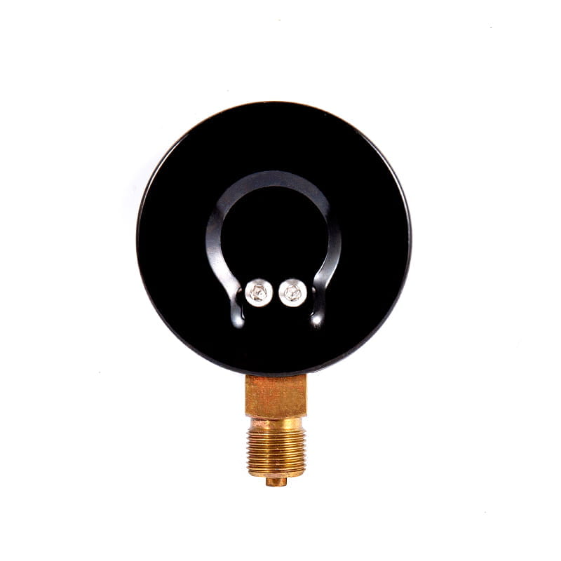
YE series micro pressure gauges/membrane box pressure gauge
Cat:Pressure Gauge
◆ Model:YE60 YE100 YE150 ◆ Use: Membrane box pressure gauge is also called micro pressure gauge....
See DetailsContent
A pressure gauge may look like one of the simplest instruments on your equipment, but it is also one of the most informative. Before the needle even moves, the gauge has already told you a great deal: what it can measure, how accurately it can measure it, where it is intended to be installed, and which approvals it carries. All of this information is expressed through symbols. The instrument codes on process drawings, the accuracy class printed on the dial, and the certification marks around the window each play a role. Learning to read these symbols helps you keep your process safe, your readings reliable, and your maintenance team confident.
The term symbol pressure gauge is used in two related ways across the industry. On one hand, it refers to the standardized graphic symbol that represents a pressure gauge in engineering documents such as P&ID diagrams, loop drawings, and instrument lists. On the other hand, it refers to the symbols and markings printed on the gauge dial and case, such as the accuracy class, pressure unit, ingress protection rating, and certification marks. Both kinds of symbols follow recognized conventions. Once you understand them, you will find it much easier to select, install, and troubleshoot pressure instrumentation.
In process plants, the quickest way to understand a measurement point is to look at the P&ID. Every pressure measurement point is shown as an instrument bubble, a circle that contains a tag code. The first letter in the code identifies the measured variable, and the second letter identifies the function of the instrument. For pressure measurements, the first letter is normally P.
The position of the bubble also carries meaning. A bubble with a horizontal line through its centre generally indicates an instrument mounted on a panel and accessible to the operator, while a bubble without a line usually represents a field-mounted instrument installed directly on the process line. Reading these details at a glance helps you understand the actual layout of the plant without leaving your desk.
Here are the pressure-related codes you will meet most often:
| Bubble code | Function | Typical location |
|---|---|---|
| PG / PGI | Local pressure gauge for direct reading | Field, on pipe or vessel |
| PI | Pressure indicator with local display | Panel or field |
| PT | Pressure transmitter with analog or digital output | Field |
| PIC | Pressure indicating controller | Panel |
| PSH / PSL | Pressure switch, high or low alarm and trip | Field or panel |
If the bubble contains PG followed by a loop number, such as PG-101, it represents a local pressure gauge installed directly on a pipe or vessel. When you see PT, the instrument is a pressure transmitter sending a 4 to 20 mA signal back to the control system. Recognising these codes quickly saves time during troubleshooting and helps you confirm that the correct symbol pressure gauge is specified for each point.
Now turn your attention from the drawing to the dial itself. Every marking on the face of a pressure gauge is there for a reason, and the most important one is the accuracy class. On a standard industrial gauge you will see a number such as 1.6 or 2.5 printed on the dial. This number represents the maximum permissible error as a percentage of the full scale. A gauge with accuracy class 1.6 and a full scale of 16 bar, for example, is allowed to deviate by no more than 0.256 bar at any point on the scale.
The scale also tells you which pressure unit the gauge uses: bar, psi, MPa, or kPa. Dual scales are common on instruments built for export. Always match the gauge unit with the unit used in your process documents so that operators do not have to convert readings under pressure.
Additional symbols indicate the environmental and safety ratings of the instrument:
| Marking or symbol | Meaning | Why it matters |
|---|---|---|
| 1.6 or 2.5 | Accuracy class: maximum error as a percentage of full scale | Determines whether the reading is acceptable for your process |
| bar / psi / MPa / kPa | Pressure unit of the scale | Must match the unit used in your process documents |
| IP65 / IP68 | Ingress protection against dust and water | Confirms suitability for outdoor or washdown environments |
| Ex d IIC T6 | Explosion-proof certification for hazardous areas | Required for safe operation in potentially explosive atmospheres |
| Red set pointer | Switch set point on electrical contact gauges | Marks the pressure at which an alarm or control action is triggered |
For electrical contact gauges, the red pointer is not a measurement reading. It marks the set point at which the internal switch will activate. Understanding these details before installation prevents costly misunderstandings and false alarms.
The majority of industrial pressure gauges use a C-shaped Bourdon tube as the sensing element. When pressure is applied, the tube tends to straighten and moves a geared pointer across the dial. Bourdon tube gauges are the workhorse of the instrumentation world, suitable for most hydraulic, pneumatic, and general process applications. They are the standard choice when the process media is compatible with copper alloy or stainless steel wetted parts.
 Y Series General Stainless Steel Pressure GaugeThis standard industrial pressure gauge handles liquid, gas, or steam that is non-corrosive to copper alloys. It suits general hydraulic and pneumatic systems where Bourdon tube construction is preferred.View Product →
When the process medium is corrosive or the pressure is very low, the sensing element changes accordingly. A diaphragm pressure gauge uses a flexible diaphragm that deflects under pressure, making it an excellent choice for chemical media and for pressure ranges below what a Bourdon tube can measure reliably. A capsule pressure gauge is a further refinement for very low gas pressures. Each construction is represented by a distinct symbol on internal drawings, so recognising the element shape is part of reading a symbol pressure gauge correctly.
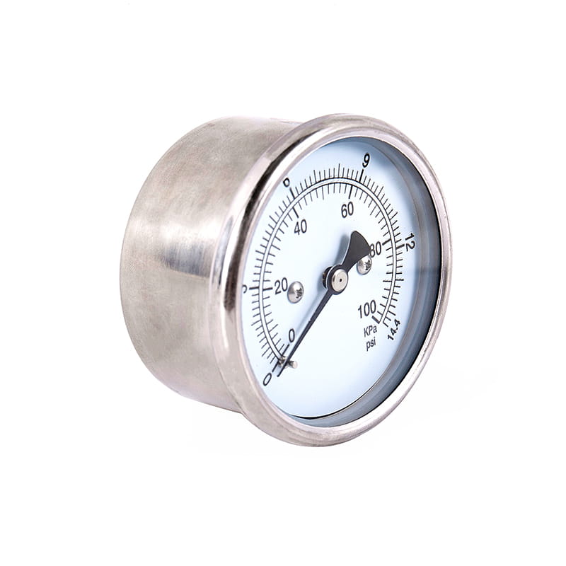 YE Series Micro Pressure Gauge with Membrane BoxDesigned for very low gas or vapor pressures, this membrane box gauge measures ranges from -40 to 40 with fine resolution, making it ideal where Bourdon tubes cannot reliably detect low pressures.View Product →
If you would like to compare the wider instrument family, our guide to different kinds of pressure gauges and how to choose one walks through the options in more detail.
Digital pressure gauges replace the mechanical pointer with an electronic display, which removes parallax error and makes readings easier in dark or vibrating locations. Electrical contact pressure gauges add a switch function for alarms and automatic control. Each type serves a different purpose, and the code on the drawing will reflect that function.
Once you can read the symbols, selection becomes a matter of matching the instrument to the real operating conditions. The engineers in our workshop recommend the following checklist:
A sudden pulsation from a reciprocating pump can destroy a standard gauge movement in weeks. In vibrating and pulsating systems, a seismic or vibration-resistant pressure gauge with a liquid-filled case protects the movement and extends service life significantly.
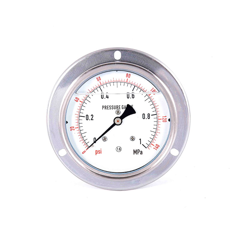 YN Series Copper Connection Seismic Pressure GaugeBuilt to withstand strong vibration and pulsation, this liquid-filled gauge offers stable readings in heavy machinery, mining, petroleum, and chemical industries where standard movements would fail quickly.View Product →
For process media that is corrosive, viscous, or prone to clogging, a diaphragm seal assembly isolates the gauge from the medium. You can read more about diaphragm seal pressure gauges when you are sizing instruments for chemical duty.
Symbols on a pressure gauge are not decoration. They are the instrument's identity card, telling you what it measures, how accurately it does so, and where it is allowed to work. Whether you are reviewing a P&ID in the control room or standing in front of a vibrating pump skid, taking a moment to read the symbols prevents mis-installation, reduces downtime, and keeps your process within the limits your engineers originally intended. And if the gauge in your hand does not match the symbol on your drawing, stop and check before you open the valve.
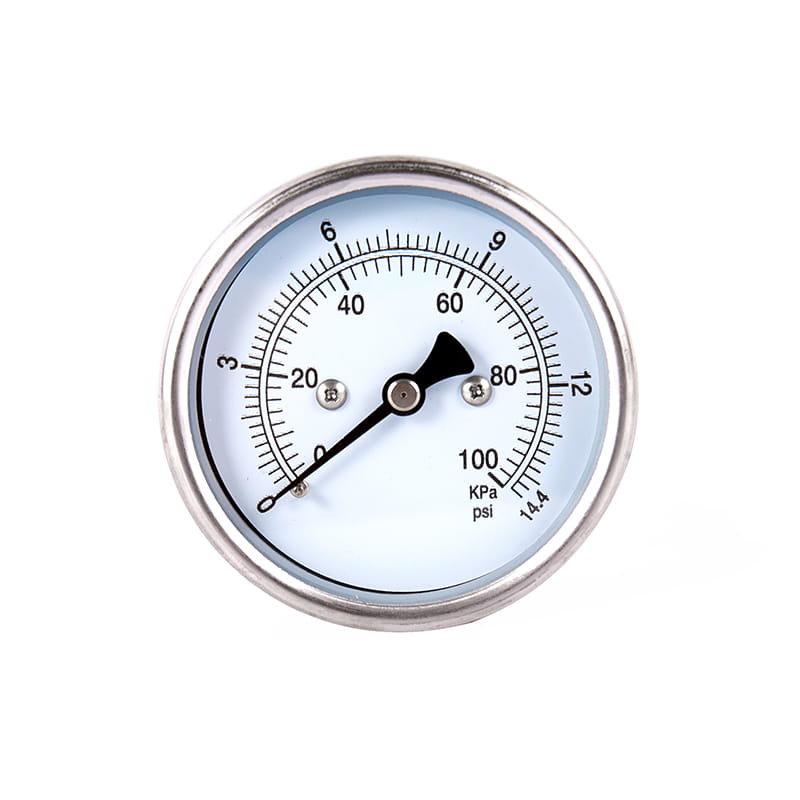
◆ Model:YE60 YE100 YE150 ◆ Use: Membrane box pressure gauge is also called micro pressure gauge....
See Details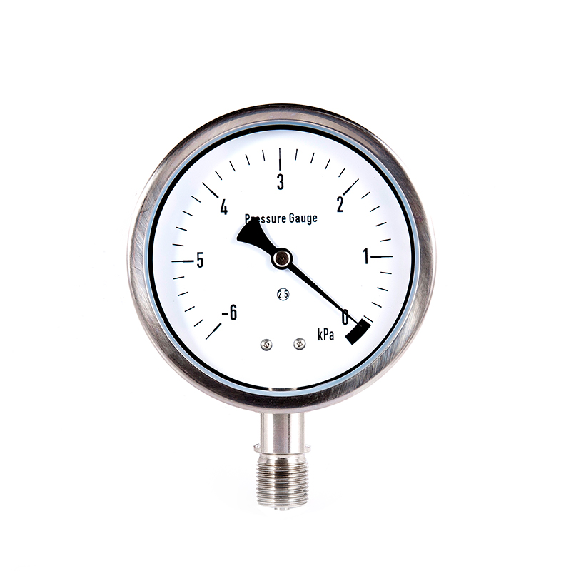
◆ Model:YEB60 YEB100 YEB150◆ Use: This series of instruments are suitable for measuring the low micr...
See Details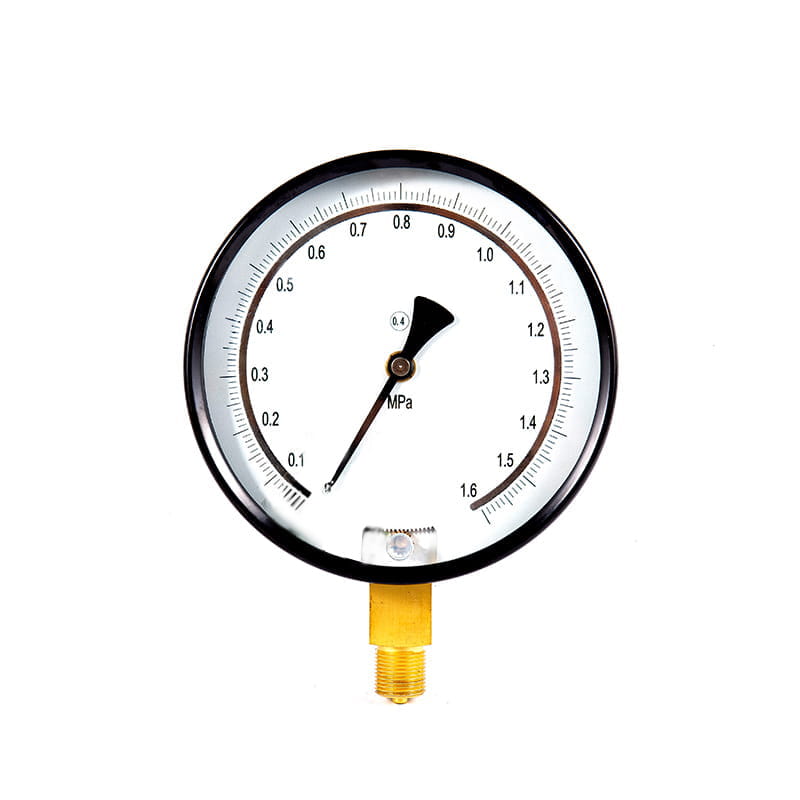
◆ Model: YJ150 YJ150A◆ Use: This series of instruments are mainly used to calibrate industrial or ci...
See Details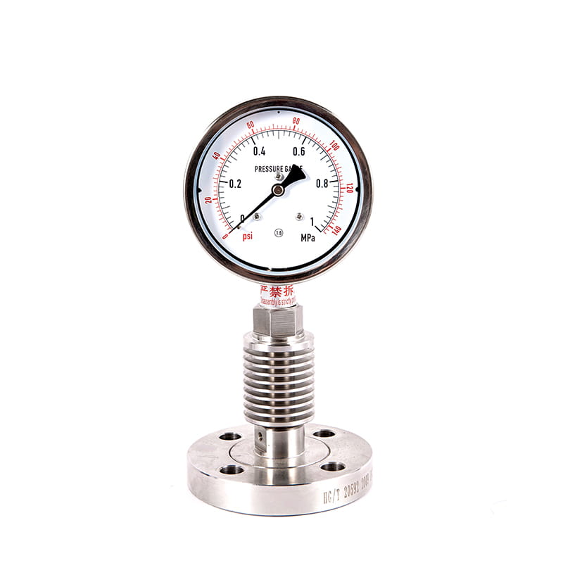
◆ Model: Y¨-ML Y¨-MF Y¨-MG Y¨-MZ Y¨-MK Y¨-MN Y¨-MS◆ Application: Due to the indirect measurement str...
See Details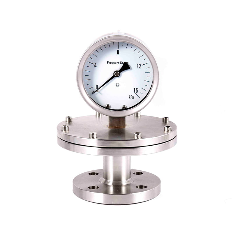
◆ Model: YP100-L YP150-L YP100-F YP150-F ◆ Application: YP series instrument diaphragm and structura...
See Details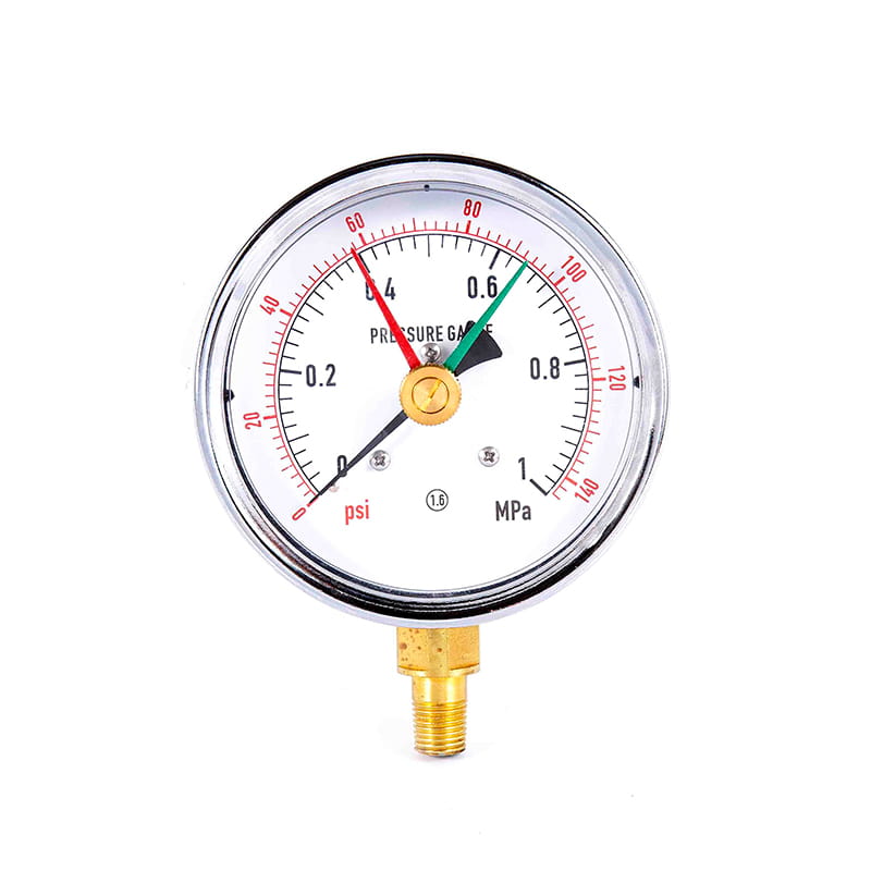
◆ Model: YD40 YD50 YD60 YD75 YD100 YD150 ◆ The main body of the instrument is a general pressure gau...
See Details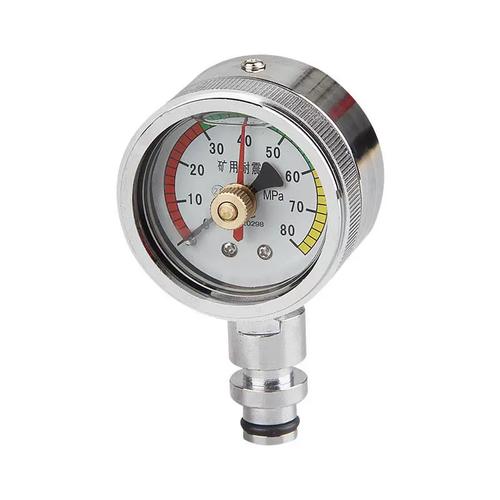
◆ Model: YKY60 ◆ Application: Mining memory pressure gauges is specially designed for underground h...
See Details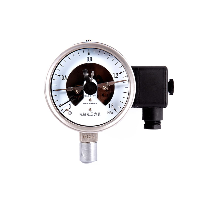
◆ Model: YXD100 YXD150 ◆ Uses: Photoelectric electric contact pressure gauge is a substitute for the...
See Details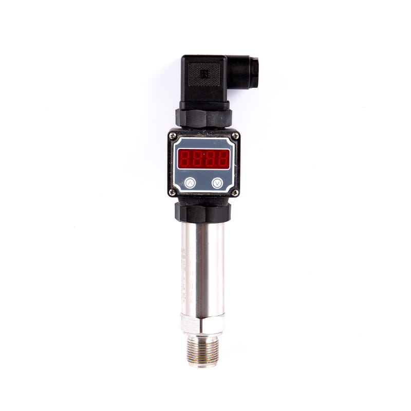
1. Overview This pressure transmitter has high sensitivity, high precision and strong anti-overload ...
See Details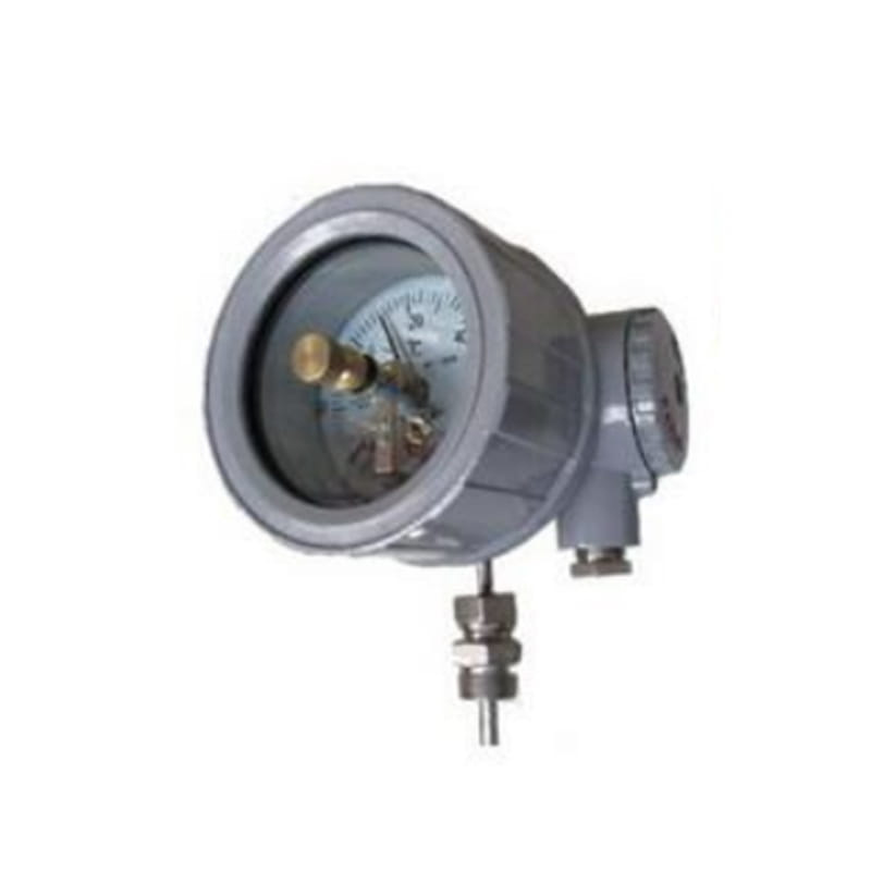
◆ Model: WSSX411B WSSX511B ◆ Introduction: This instrument is in accordance with the national standa...
See Details


