
 English
 русский
 Español
 عربى
عربى
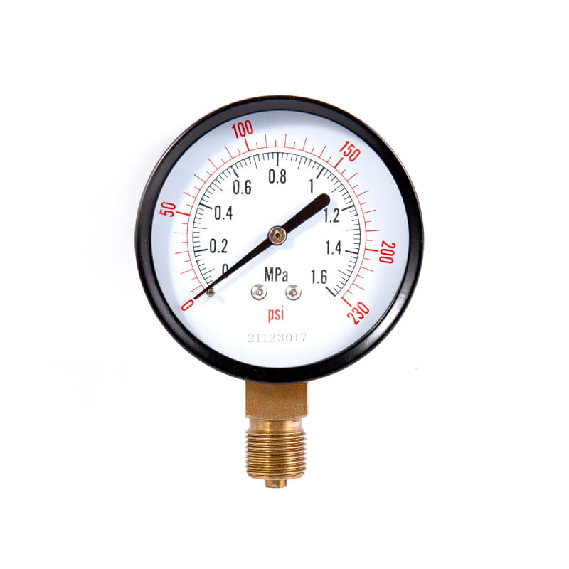
YLm series refrigerant pressure gauge
Cat:Pressure Gauge
◆ Model: YLm60 YLm100 YLm150◆ Application: This series of instruments are special instruments for de...
See DetailsContent
Pressure gauges are among the most commonly installed instruments in any industrial facility, yet they are also among the most frequently misspecified. Walk through any process plant, compressed air system, or hydraulic circuit and you will find pressure gauges — some reading accurately and reliably, others vibrating beyond readability, corroded by incompatible process media, or simply installed in the wrong pressure range for the application. The consequences range from inconvenient — an unreadable gauge that provides no useful information — to dangerous, where an incorrectly specified gauge fails structurally under overpressure conditions. Understanding the different types of pressure gauges, the specifications that determine their suitability for specific applications, and the installation and maintenance practices that extend their service life is fundamental knowledge for process engineers, maintenance technicians, and instrumentation professionals working with pressurized systems of any kind.
Most industrial pressure gauges use a mechanical sensing element that deforms under applied pressure — the elastic deformation of the sensing element is mechanically linked to a pointer that moves across a calibrated scale, converting the physical deformation into a readable pressure indication. The Bourdon tube is the most widely used sensing element in industrial gauges: it is a curved or helical tube of oval or elliptical cross-section, sealed at one end (connected to the pointer mechanism) and open at the other end (connected to the process connection). When internal pressure is applied, the tube tends to straighten due to the pressure differential acting on its curved geometry, and this straightening motion — amplified through a gear and lever mechanism called the movement — drives the pointer across the scale. The elegance of the Bourdon tube is its combination of simplicity, reliability, and wide pressure range capability — Bourdon tube gauges accurately measure pressures from below 1 bar to above 10,000 bar depending on the tube material, wall thickness, and geometry.
For lower pressure ranges — typically below 0.6 bar — where the Bourdon tube lacks sufficient sensitivity, diaphragm and capsule sensing elements are used instead. A diaphragm gauge uses a thin corrugated disc clamped between two flanges as its sensing element; pressure applied to one face of the diaphragm causes it to deflect, and this deflection is transmitted to the pointer mechanism. Capsule gauges use two corrugated diaphragms welded together at their perimeters to form a sealed capsule — pressure applied externally or internally causes the capsule to expand or contract, providing greater sensitivity than a single diaphragm for the measurement of very low pressure differentials. These sensing technologies determine the gauge's fundamental pressure range capability and should be matched to the expected process pressure range before any other specification is considered.
Before selecting a pressure gauge, it is essential to understand which type of pressure is being measured — gauge pressure, absolute pressure, or differential pressure — as these are fundamentally different quantities that require different gauge types and produce results that cannot be directly compared without correction.
Selecting the correct pressure gauge for an application requires matching a set of interdependent specifications to the process conditions, installation environment, and accuracy requirements of the measurement point. The following table summarizes the most important parameters and their practical significance.
| Specification | Typical Range / Options | What It Determines |
| Pressure Range | Vacuum to 10,000+ bar | Scale coverage; sensing element selection |
| Dial Size | 40 mm – 250 mm | Readability at distance; scale graduation |
| Accuracy Class | 0.1 / 0.25 / 0.6 / 1.0 / 1.6 / 2.5 | Maximum error as % of full scale |
| Process Connection | G 1/4, G 1/2, NPT 1/4, NPT 1/2 (common) | Compatibility with pipe/manifold threads |
| Connection Position | Bottom entry, back entry, back-center | Installation orientation and piping layout |
| Wetted Material | Brass, 316SS, Monel, Hastelloy, PTFE-lined | Chemical compatibility with process fluid |
| Case Material | Phenolic, ABS, stainless steel, aluminum | Corrosion resistance; impact protection |
| IP / Protection Rating | IP54 – IP68 | Resistance to dust and water ingress |
| Filling (Liquid) | Dry, glycerine-filled, silicone-filled | Vibration and pulsation damping |
The pressure range of the gauge should be selected so that the normal operating pressure falls within the middle third of the scale — typically between 25% and 75% of the full scale pressure, with the ideal operating point at approximately 50 to 65% of full scale. Operating a gauge consistently at the top of its range subjects the sensing element to stresses near its elastic limit, accelerating fatigue and reducing service life. Operating it at the very bottom of the range reduces reading resolution and makes subtle pressure changes difficult to detect. The lower end of the range should accommodate any expected pressure transients or surge conditions without exceeding the gauge's specified overpressure limit — typically 130% of full scale for standard gauges.
The wetted materials of a pressure gauge — the Bourdon tube, socket (process connection body), and any internal wetted fittings — must be chemically compatible with the process fluid. Incompatibility causes corrosion or stress corrosion cracking of the sensing element, leading to measurement drift, structural failure, or sudden fracture that can release pressurized process fluid from the gauge case. The following material selection guidance covers the most common industrial fluid categories.
Liquid-filled pressure gauges — typically filled with glycerine (glycerol) or silicone oil — are specified for applications involving pulsating pressure, vibration, or where the gauge is mounted directly on vibrating equipment such as pumps, compressors, and reciprocating engines. The liquid filling provides two distinct benefits: it damps the oscillation of the pointer caused by pressure pulsations (which causes dry gauge pointers to vibrate visibly and makes reading impossible while also accelerating movement wear), and it lubricates the movement mechanism to reduce friction and wear from vibration-induced micro-movement of the gear and lever components.
Glycerine-filled gauges are suitable for ambient and moderate temperatures — typically -20°C to +60°C — and are not appropriate for outdoor installation where freezing temperatures occur, as glycerine freezes at approximately -12°C (pure glycerine) to -40°C depending on water content. Silicone-filled gauges have a much wider temperature range — typically -60°C to +200°C — and are the correct choice for outdoor installation in cold climates, high-temperature service applications, or where the gauge may be exposed to direct solar heat in process plant enclosures. Both filling types make the gauge case and window opaque at the back and sides but provide a clear front face for reading. Glycerine and silicone-filled gauges are more expensive than dry gauges and require a sealed case to prevent fill fluid loss — the case material and window sealing quality are therefore more critical quality parameters for filled gauges than for dry equivalents.
Pressure gauge accuracy is defined by its accuracy class — a number representing the maximum permissible error as a percentage of the full scale range, measured at any point on the scale under reference conditions (typically 20°C ambient, upright installation). A Class 1.0 gauge with a 0 to 10 bar range has a maximum permissible error of ±0.1 bar at any point on its scale. A Class 2.5 gauge with the same range has a maximum permissible error of ±0.25 bar — 2.5 times less accurate. The class designation follows the EN 837 standard in European practice and ASME B40.100 in North American practice.
For most process monitoring and safety indication applications, accuracy Class 1.6 or Class 2.5 is adequate — the gauge provides sufficient accuracy to monitor process conditions, identify trends, and alert operators to significant deviations. For applications where the gauge reading is used directly for process control decisions, setpoint verification, or calibration reference, Class 1.0 or better is appropriate. Test gauges used as calibration references are typically Class 0.25 or Class 0.1, with precision movements and larger dial diameters that allow finer scale graduation for interpolation of readings between graduation marks. It is economically wasteful and operationally unnecessary to specify high-accuracy Class 0.25 gauges for general process monitoring applications — the additional cost provides no operational benefit if the application does not require the higher accuracy, and precision gauges are more susceptible to damage from the pulsation and vibration present in most industrial environments.
A correctly specified pressure gauge installed incorrectly will not deliver its rated performance or service life. Several installation practices consistently prevent the most common causes of gauge failure and inaccuracy in industrial applications.
Pressure gauges are often treated as permanently installed, maintenance-free instruments — an approach that leads to gauges that are mechanically intact but reading inaccurately, or gauges that fail structurally without warning because degradation went undetected. A systematic maintenance approach protects both measurement integrity and personnel safety in pressurized system environments.
Calibration verification — comparing the gauge reading against a certified reference gauge or deadweight tester at multiple points across the scale — should be performed on all gauges used for process control or safety functions at intervals determined by the criticality of the measurement and the gauge's historical stability. For safety-critical applications such as boiler pressure indication, pressure vessel relief valve setpoint verification, and compressed gas cylinder gauges, annual calibration verification is typically the minimum acceptable interval, with more frequent checks for gauges in harsh environments or high-cycle service.
Pressure gauges are deceptively simple instruments with consequences that are anything but simple when they are incorrectly specified, improperly installed, or inadequately maintained. The engineering discipline of matching gauge type, pressure range, wetted material, filling, accuracy class, and case rating to the specific process conditions and environmental demands of each measurement point — combined with systematic installation, calibration, and replacement practices — is the foundation of reliable pressure measurement across every pressurized system in any industrial facility.

◆ Model: YLm60 YLm100 YLm150◆ Application: This series of instruments are special instruments for de...
See Details
◆ Model: YC40 YC50 YC60 YC75 YC100 YC150◆ Use: This series of instruments are suitable for measuring...
See Details
◆ Model: YJY100 YJY150◆ Use: Absolute pressure refers to the pressure which is higher than absolute ...
See Details
◆ Model: YP100-L YP150-L YP100-F YP150-F ◆ Application: YP series instrument diaphragm and structura...
See Details
◆ Model: YXD100 YXD150 ◆ Uses: Photoelectric electric contact pressure gauge is a substitute for the...
See Details
1. Overview This air pressure transmitter has high sensitivity, high precision and strong anti-overl...
See Details
◆ Model: WSS-3 WSS-4 WSS-5 ◆ Application: Bimetal thermometer has the characteristics of no mercury ...
See Details
◆ Model: WSZC-2 ◆ Overview: The transmitter is composed of advanced circuit module integration techn...
See Details
The Valve remote control and liquid level telemetry system enhances operational efficiency by provid...
See Details
The Float level gauge UHB is engineered for high-precision measurement, providing accurate and relia...
See Details


