

 English
 русский
 Español
 عربى

YE series micro pressure gauges/membrane box pressure gauge
Cat:Pressure Gauge
◆ Model:YE60 YE100 YE150 ◆ Use: Membrane box pressure gauge is also called micro pressure gauge....
See DetailsThe core of pressure transmitter commissioning lies in safe isolation, loop wiring, parameter configuration, and pressure calibration. The following are the standard on-site commissioning procedures:
Process isolation: Close the root valve, then depressurize and drain the impulse lines. If the measuring point is involved in interlock logic, a work permit must be obtained and the interlock must be bypassed/deactivated as per regulations.
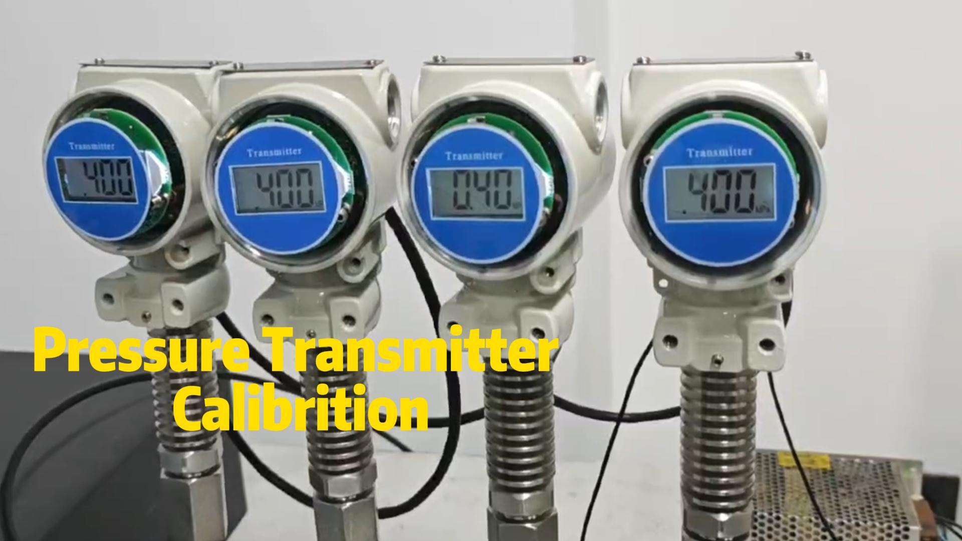
Tools and parameter confirmation:Prepare a standard pressure source, multimeter, HART communicator, and 24V DC power supply. Verify the transmitter tag number, range (LRV/URV), unit, and other original parameters.
2. Electrical Wiring and Power-On
The most common configuration is the two-wire 4–20 mA loop:
Loop wiring: Connect the positive terminal of the 24V DC power supply to the "+" terminal of the transmitter. Connect the "−" terminal of the transmitter to the AI+ of the PLC/DCS, and finally return from the AI− to the negative terminal of the power supply to form a closed loop.
Shield grounding: Use shielded twisted-pair cable for the signal line. The shield should be grounded at only one end, on the control cabinet side, while the transmitter side is left floating.
Power-on warm-up: Close the circuit and power on the transmitter. Allow 2–5 minutes for the internal components to stabilize.
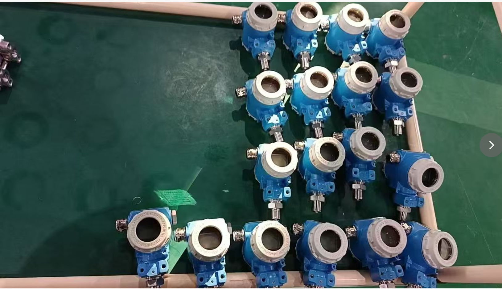
3. Basic Parameter Configuration (Using HART Communicator) Connect the HART communicator in parallel across the loop terminals (ensure there is a ≥250Ω resistor in series in the loop):
Communication connection: Power on the communicator; it will automatically identify the device and establish communication.
Basic settings: Sequentially set the measurement unit, damping time, output mode (normally linear), and failure alarm direction.
Range setting: Enter the range menu and set the lower range value (LRV, corresponding to 4 mA) and upper range value (URV, corresponding to 20 mA).
4. Zero and Span Calibration
Red line: Before zero calibration, confirm that the transmitter is under true zero pressure. Calibration with pressure applied is strictly prohibited.
Zero Trim: Vent the transmitter to atmosphere (or apply the LRV standard pressure). After the pressure stabilizes, perform a zero trim using the HART communicator to make the output exactly 4 mA.
Span Trim: Apply the full-scale pressure to the transmitter using a standard pressure source. After stabilization, perform a span trim to make the output exactly 20 mA.
Repeat Verification: Slowly increase pressure through the five check points of 0%, 25%, 50%, 75%, and 100%, and record the readings. Then decrease the pressure and record the readings in reverse. Calculate whether the basic error and hysteresis are within the acceptable limits.
5. Restoration and Commissioning
Loop Re-check: Remove the standard pressure source and restore the original process piping connections.
System Comparison: Notify the control room and compare the pressure value, range, and engineering unit displayed on the DCS/PLC with the on-site readings to ensure they are fully consistent.
Interlock Restoration: After confirming the entire loop operates normally and is leak-free, restore the interlock protection and officially put the transmitter into service.
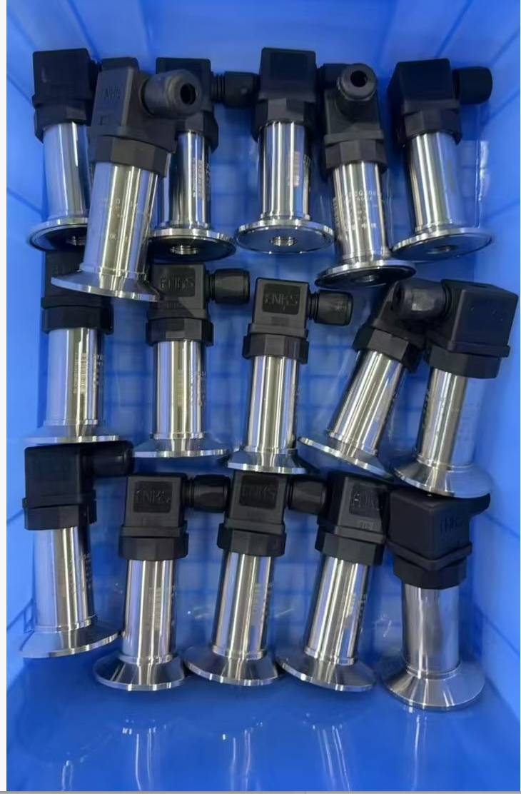
What are your working conditions and medium projects?
I can help you check the corresponding test items and recommend product models.
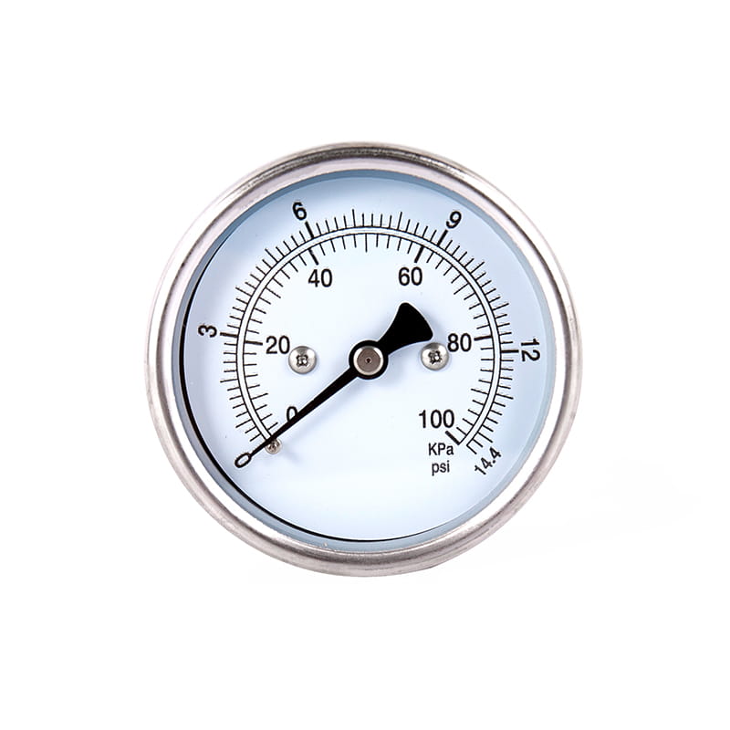
◆ Model:YE60 YE100 YE150 ◆ Use: Membrane box pressure gauge is also called micro pressure gauge....
See Details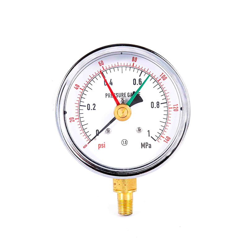
◆ Model: YD40 YD50 YD60 YD75 YD100 YD150 ◆ The main body of the instrument is a general pressure gau...
See Details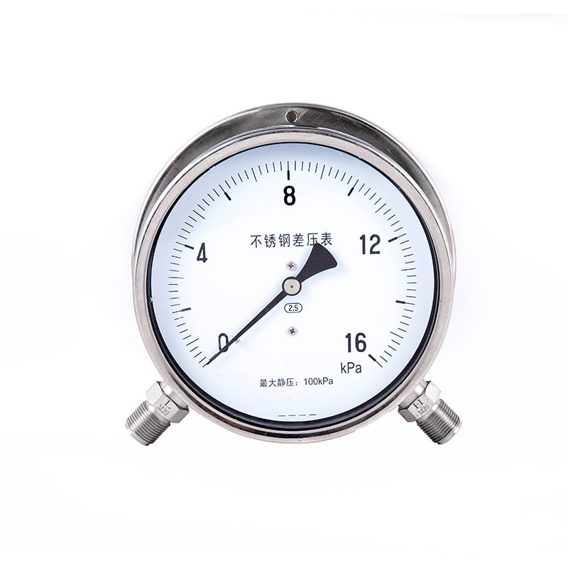
◆ Model: CYB100 CYB150 ◆ Application: Stainless steel differential pressure gauges is suitable for m...
See Details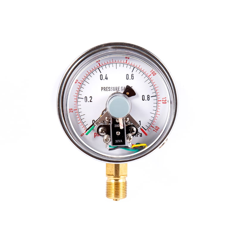
◆ Model: YXCh100 YXCh150 ◆ Application: Reed electric contact pressure gauge is suitable for measuri...
See Details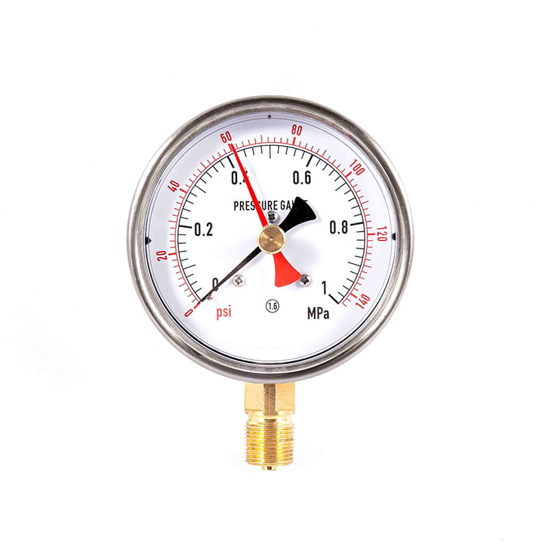
◆ Model: YZS102 ◆ Application: Double-needle double-tube pressure gauges is mainly used in rolling ...
See Details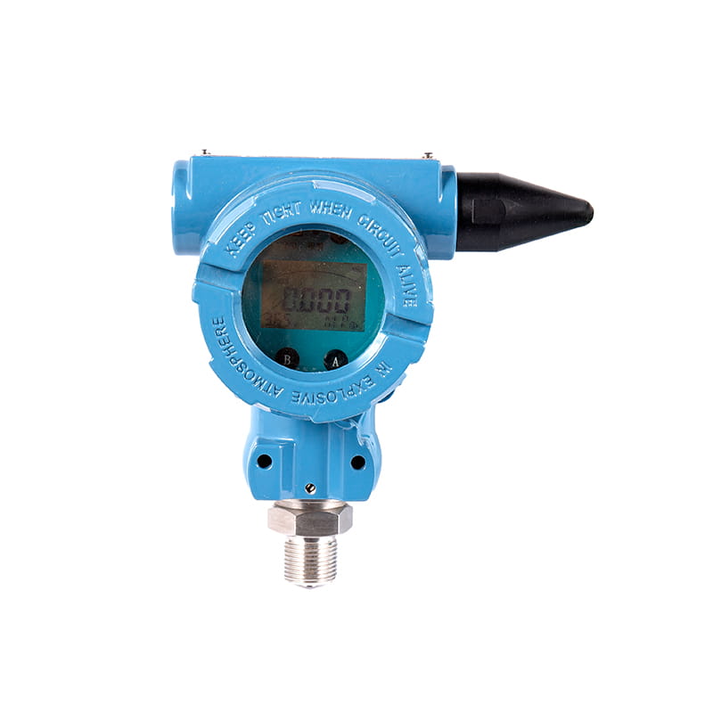
1. Overview This pressure transmitter has high sensitivity, high precision and strong anti-overload ...
See Details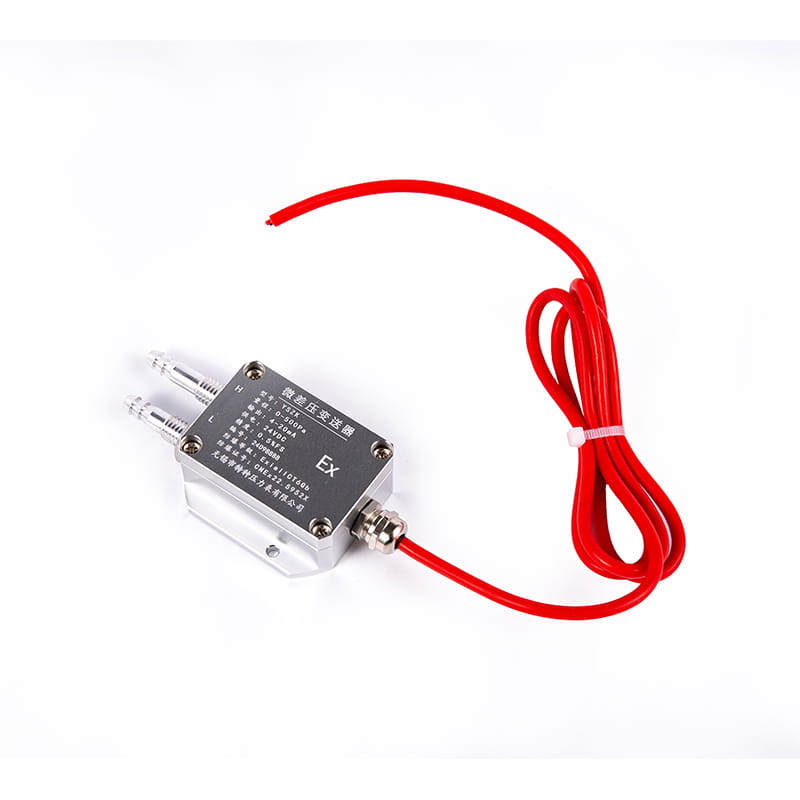
1. Overview This air pressure transmitter has high sensitivity, high precision and strong anti-overl...
See Details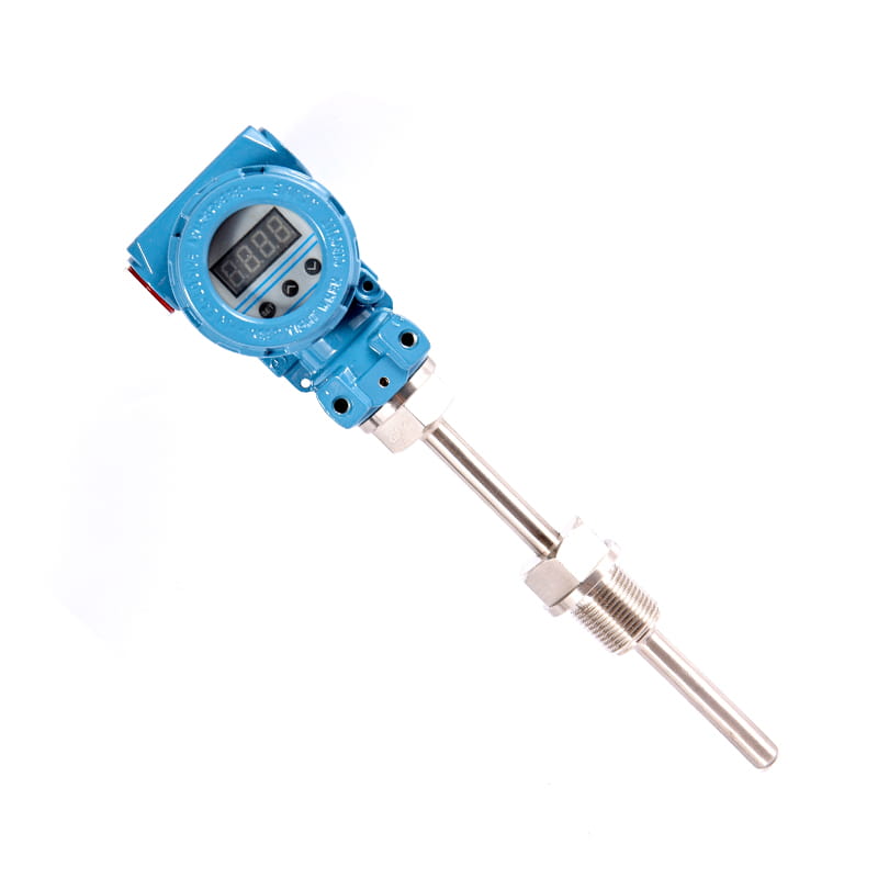
◆ Model: WSZC-2 ◆ Overview: The transmitter is composed of advanced circuit module integration techn...
See Details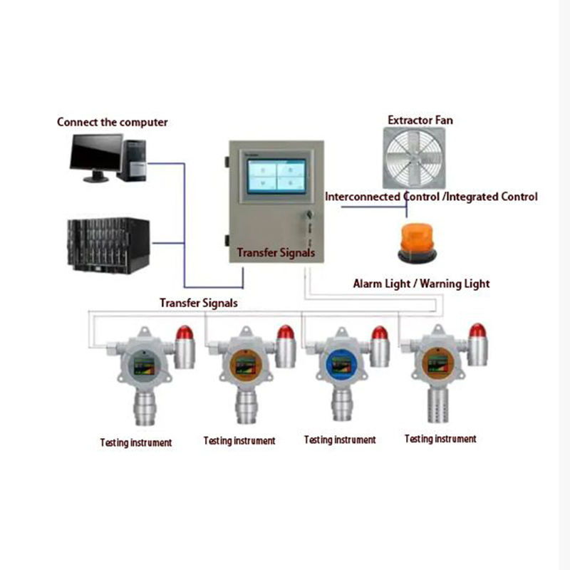
The gas monitoring alarm system is designed for optimal safety and usability. It features a user-fri...
See Details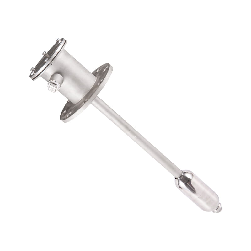
The Float level controller UHK features a simple structure that ensures easy installation and mainte...
See Details


