
 English
 русский
 Español
 عربى
عربى
YE series micro pressure gauges/membrane box pressure gauge
Cat:Pressure Gauge
◆ Model:YE60 YE100 YE150 ◆ Use: Membrane box pressure gauge is also called micro pressure gauge....
See DetailsContent
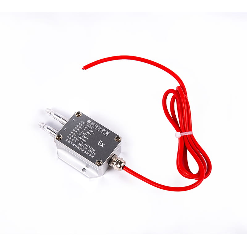
A wind pressure transmitter is an electronic instrument that measures the static or differential pressure exerted by moving air or wind and converts that measurement into a standardized electrical output signal — typically 4–20 mA, 0–10 V DC, or a digital protocol such as RS-485 Modbus — that can be read by a controller, data logger, or building management system. Unlike simple mechanical pressure gauges that provide a local visual reading, a wind pressure transmitter continuously monitors pressure and transmits a live signal to remote monitoring equipment, enabling real-time process control, safety interlock activation, and long-term data trending without requiring an operator to be physically present at the measurement point.
Wind pressure transmitters are deployed across a remarkably wide range of industries and applications. In HVAC and building automation systems, they monitor static pressure in air ducts, fan inlet and outlet pressures, filter differential pressure, and room-to-corridor pressure differentials in cleanrooms or isolation wards. In meteorology and wind energy, they measure wind-induced dynamic pressure on structures, anemometer reference pressures, and wind load on turbine nacelles. In industrial process environments, they monitor draft pressure in furnaces and boilers, stack pressure in exhaust systems, and air pressure in pneumatic conveying lines. In aerospace and automotive testing, they measure wind tunnel test section pressure distributions with very high accuracy. The physical measurement principle remains consistent across all these applications, but the specific sensing technology, pressure range, accuracy class, and environmental protection rating required vary substantially between them.
The core of any wind pressure transmitter is its sensing element — the physical transducer that converts applied pressure into an electrical quantity. Several distinct sensing technologies are used in commercially available wind pressure transmitters, each with different performance characteristics, temperature stability, overrange tolerance, and cost profiles that make them more or less suitable for specific applications.
Piezoresistive sensors are the most widely used technology in general-purpose wind pressure transmitters. A thin silicon diaphragm with four piezoresistive strain gauge resistors diffused into its surface deflects under applied pressure, changing the resistance values in the Wheatstone bridge circuit formed by the resistors. This resistance change is amplified and converted to the output signal by the transmitter's signal conditioning electronics. Silicon piezoresistive sensors offer excellent sensitivity, fast response times typically below 10 milliseconds, and compatibility with MEMS (micro-electromechanical systems) manufacturing processes that enable very small sensor geometries suitable for low-pressure measurement ranges. Their primary limitation is moderate temperature sensitivity — the piezoresistive coefficients of silicon change with temperature, requiring active temperature compensation circuitry to maintain accuracy across wide operating temperature ranges.
Capacitive pressure sensors measure the change in capacitance between a flexible diaphragm electrode and a fixed reference electrode as the diaphragm deflects under pressure. Because capacitance measurement is inherently less temperature-sensitive than piezoresistance, capacitive sensors offer better long-term stability and lower temperature error than piezoresistive alternatives, particularly important in outdoor wind monitoring applications where ambient temperature swings of 60°C or more between summer and winter are common. Capacitive sensors are also inherently overrange-tolerant because the diaphragm simply contacts the fixed electrode rather than yielding plastically when pressure greatly exceeds the rated range. This makes them robust in applications where pressure surges or transients occur, such as measuring wind gusts on exposed structures.
Ceramic sensing elements use an alumina ceramic diaphragm with thick-film strain gauges screen-printed directly onto its surface. The ceramic material is chemically inert and highly resistant to corrosion, making these sensors suitable for harsh environments where exposure to moisture, condensation, salt air, or mildly corrosive gases is anticipated. Ceramic elements do not require oil fill — a significant advantage in applications where oil contamination of the process medium is unacceptable. They are commonly found in outdoor meteorological wind pressure transmitters and marine applications where the sensing port may be directly exposed to humid or saline atmospheric conditions over years of continuous service.
Understanding the distinction between differential and static pressure measurement is essential when specifying a wind pressure transmitter, as the two measurement modes require different instrument configurations and installation approaches even when measuring what is broadly described as "wind pressure."
Static pressure measurement quantifies the pressure at a single point in the airflow relative to a reference — either atmospheric pressure (gauge measurement) or absolute vacuum (absolute measurement). In duct systems and building pressurization applications, static pressure transmitters monitor whether a controlled space is maintained at the design positive or negative pressure relative to the surrounding environment. A single pressure port connects the transmitter to the measurement point, and the reference is either the local atmosphere or a sealed internal reference chamber.
Differential pressure measurement quantifies the pressure difference between two specific points in the airflow simultaneously. Wind pressure transmitters configured for differential measurement have two pressure ports — a high-pressure port and a low-pressure port — and output a signal proportional to the difference between the pressures applied to each. This configuration is used to measure the pressure drop across filters, heat exchangers, and fan assemblies in HVAC systems; to calculate airflow velocity using a Pitot tube in conjunction with Bernoulli's equation; and to measure the pressure difference between the windward and leeward faces of a structure to quantify wind load. The differential pressure range of these instruments is typically very low — from a few Pascals to a few kilopascals — requiring high-sensitivity sensing elements and careful installation to achieve accurate results.
The specification sheet of a wind pressure transmitter contains numerous parameters, but not all of them have equal relevance to real-world measurement performance. The following specifications have the greatest practical impact on whether a transmitter will meet the accuracy, reliability, and longevity requirements of a wind pressure measurement application.
| Specification | Typical Range | Why It Matters |
| Pressure Range | 0–10 Pa to 0–10 kPa | Must encompass full expected wind pressure variation with margin |
| Total Accuracy | ±0.1% to ±2% FS | Determines measurement uncertainty across full operating conditions |
| Temperature Error | ±0.1% to ±0.5% FS per 10°C | Critical for outdoor applications with large temperature swings |
| Response Time | 10 ms to 500 ms | Determines ability to capture fast wind gust transients accurately |
| Overrange Pressure | 3× to 10× rated range | Protects sensor from damage during unexpected wind pressure spikes |
| IP Protection Rating | IP54 to IP67 | Defines resistance to dust ingress and water exposure |
| Output Signal | 4–20 mA, 0–10 V, RS-485 | Must be compatible with receiving controller or data logger |
| Operating Temperature | -40°C to +85°C | Must cover full expected ambient temperature range at installation site |
Total accuracy is the most frequently misunderstood specification in pressure transmitter datasheets. Manufacturers sometimes quote only the linearity or hysteresis error of the sensing element at a single reference temperature, which presents a best-case figure that does not reflect the combined error from all sources — linearity, hysteresis, repeatability, and temperature effect — across the full operating temperature range. Always request the total error band (TEB) figure that combines all error sources at the extremes of the operating temperature range, as this is the number that determines worst-case measurement uncertainty in real installation conditions.
Even a high-specification wind pressure transmitter will deliver poor measurement results if it is installed incorrectly. The installation configuration — including the orientation of the transmitter body, the design and positioning of pressure taps, the routing of impulse lines, and the management of condensation — has a direct and significant impact on the accuracy and reliability of the measurement in service.
For wind pressure measurement on building facades and structures, the pressure tap — the opening through which atmospheric pressure is sensed — must be positioned to measure true static pressure without dynamic (velocity) pressure interference. A poorly designed pressure tap oriented directly into the wind stream will sense a combination of static and dynamic pressure, producing readings significantly higher than the true static wind pressure. The standard solution is a static pressure port with a rounded or chamfered entry geometry oriented perpendicular to the local flow direction, or a multi-hole averaging manifold that cancels out directional velocity pressure components across multiple measurement points. In duct applications, pressure taps should be located in straight duct sections at least five duct diameters downstream and two diameters upstream of any bends, dampers, or obstructions that would create turbulent flow patterns affecting the static pressure reading.
When a wind pressure transmitter is mounted remotely from its pressure measurement point, impulse lines — small-bore tubes or hoses connecting the pressure tap to the transmitter ports — carry the pressure signal to the instrument. Air or gas trapped in impulse lines does not affect pressure transmission accuracy significantly, but liquid accumulation in lines intended for gas service creates a hydrostatic head error proportional to the height of the liquid column. In outdoor wind pressure measurement applications where condensation is expected, impulse lines should be routed with a continuous downward slope from the measurement point to the transmitter so that any condensed moisture drains away from the transmitter rather than accumulating at low points. Alternatively, condensate pots installed at low points in the impulse line system collect and periodically drain accumulated liquid to prevent it from entering the transmitter ports.
Many differential pressure transmitters exhibit a small zero offset shift when their orientation changes from the factory calibration position. This occurs because the weight of the sensing diaphragm creates a small but measurable gravitational load when the transmitter is mounted in a non-vertical orientation. For very low pressure range instruments measuring wind pressures of 10–100 Pa, this gravitational zero offset can represent a significant fraction of the full-scale output. Most manufacturers specify the zero shift per 90° of tilt from vertical, allowing the installer to apply a correction factor or to perform an in-situ zero calibration after the transmitter is mounted in its final orientation. Always perform this field zero adjustment before commissioning any low-range wind pressure transmitter to eliminate orientation-induced zero error from the measurement.
Matching a wind pressure transmitter to its application requires balancing performance requirements against environmental constraints and budget. The following guidelines summarize the most important selection criteria for the major application categories.
A wind pressure transmitter is a precision measurement instrument whose accuracy degrades over time due to mechanical drift in the sensing element, changes in the signal conditioning electronics, and physical changes to the pressure ports from contamination or corrosion. Establishing a calibration and maintenance program appropriate to the application's accuracy requirements is essential to ensuring that the transmitter continues to deliver reliable measurements throughout its service life.
Calibration interval should be determined by the combination of the transmitter's specified long-term stability — typically expressed as a percentage of full scale per year — and the accuracy requirement of the application. A transmitter with ±0.1% FS per year drift installed in an application requiring ±0.5% FS total accuracy can theoretically operate for several years between calibrations before its accumulated drift contributes significantly to total error. In practice, most industrial installations calibrate pressure transmitters annually using a portable precision pressure calibrator traceable to national measurement standards, with the calibration results documented for quality management system compliance. Safety-critical applications such as cleanroom pressurization in pharmaceutical manufacturing or wind load monitoring on occupied structures may require semi-annual or quarterly calibration intervals.
Routine maintenance of wind pressure transmitters should include periodic inspection and cleaning of pressure ports to remove dust, insect debris, or biological growth that can partially block the sensing opening and cause artificially low pressure readings. In outdoor applications, the pressure tap screen or filter — if fitted — should be inspected after severe weather events and replaced if damaged or blocked. Cable entry glands should be checked for integrity and resealed if any signs of moisture ingress are detected at the junction between the cable and the transmitter housing. Transmitters showing signs of physical damage to the housing, corroded pressure ports, or signal output behavior inconsistent with the known process conditions should be replaced rather than repaired, as field repair of precision pressure sensing elements is rarely practical or cost-effective compared to replacement with a new calibrated unit.

◆ Model:YE60 YE100 YE150 ◆ Use: Membrane box pressure gauge is also called micro pressure gauge....
See Details
◆ Model:YEB60 YEB100 YEB150◆ Use: This series of instruments are suitable for measuring the low micr...
See Details
◆ Model: YQ40 YQ50 YQ60 YQ75 YQ100 YQ150◆ Use: This series of gauges are all made of stainless steel...
See Details
◆ Model: YJY100 YJY150◆ Use: Absolute pressure refers to the pressure which is higher than absolute ...
See Details
◆ Model: YXCm100 YXCm150 ◆ Uses: This kind of instrument is an ideal alternative to the magnetic-ass...
See Details
◆ Model: YS100 YS150◆ Introduction: This digital pressure gauge has beautiful shape, stable performa...
See Details
1. Overview This pressure transmitter has high sensitivity, high precision and strong anti-overload ...
See Details
◆ Model: WSS-3 WSS-4 WSS-5 ◆ Application: Bimetal thermometer has the characteristics of no mercury ...
See Details
◆ Model: WSSX-4 ◆ Application: The electric contact bimetal thermometer has the characteristics of n...
See Details
The SIS System is engineered to provide exceptional security and reliability in hazardous environme...
See Details


