
 English
 русский
 Español
 عربى
عربى
YLm series refrigerant pressure gauge
Cat:Pressure Gauge
◆ Model: YLm60 YLm100 YLm150◆ Application: This series of instruments are special instruments for de...
See DetailsContent
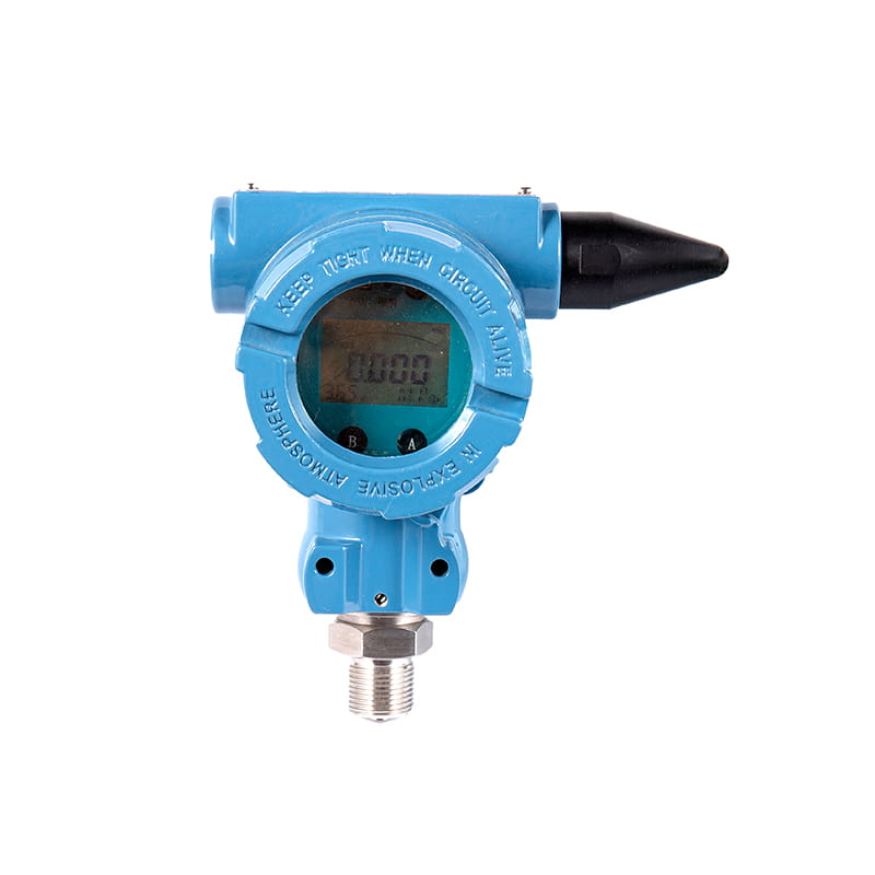
A pressure transmitter is a device used to measure pressure in liquids, gases, or steam and convert that measurement into an electrical signal. This signal, typically in the form of 4-20mA, voltage, or digital output, can be transmitted to a control system, display unit, or data logger. Pressure transmitters are essential components in industries such as oil and gas, water treatment, HVAC, food processing, and pharmaceuticals, where accurate pressure monitoring is critical for safety, efficiency, and process control.
Unlike simple pressure gauges that provide a local visual reading, pressure transmitters allow remote monitoring and integration with automated systems such as PLCs (Programmable Logic Controllers) and SCADA (Supervisory Control and Data Acquisition) systems. This makes them indispensable for modern industrial automation.
A pressure transmitter operates by detecting pressure changes through a sensing element, then converting this physical change into a proportional electrical signal. The process generally involves three main stages.
The sensing element, often a diaphragm or strain gauge, deforms slightly when exposed to pressure. This deformation is the foundation of the measurement process. Common sensor technologies include piezoresistive, capacitive, and resonant sensors, each offering different levels of accuracy, sensitivity, and durability depending on the application.
Once the sensing element detects a change in pressure, this mechanical deformation is converted into an electrical signal. The signal conditioning circuit amplifies, filters, and linearizes the raw signal to ensure accuracy across the entire measurement range.
The processed signal is then transmitted to a control system or display device. Standard output formats include analog signals like 4-20mA or 0-10V, and digital protocols such as HART, Modbus, or Profibus, which allow for additional diagnostic information to be communicated alongside the pressure reading.
Selecting the right pressure transmitter depends on the specific application requirements. Below is an overview of the most widely used types and their typical applications.
| Type | Measurement Principle | Typical Application |
| Gauge Pressure | Measures relative to atmospheric pressure | Tank level monitoring, pump systems |
| Absolute Pressure | Measures relative to a perfect vacuum | Vacuum systems, altitude sensing |
| Differential Pressure | Measures the difference between two points | Flow measurement, filter monitoring |
| Sealed Pressure | Measures relative to a fixed sealed reference | Sealed enclosures, hydraulic systems |
Selecting the correct pressure transmitter requires careful consideration of several technical and environmental factors. Making the wrong choice can lead to inaccurate readings, premature failure, or costly downtime.
Proper installation significantly impacts the performance and lifespan of a pressure transmitter. Mounting the device in a location free from excessive vibration and temperature fluctuations helps maintain measurement accuracy over time. Where possible, install the transmitter close to the process connection point to minimize tubing length, which can introduce signal lag or pressure loss.
Regular maintenance includes checking for leaks at process connections, verifying calibration against a known reference standard, and inspecting wiring and seals for signs of wear or corrosion. Many industrial facilities establish a calibration schedule, often annually or biannually, depending on the criticality of the application and regulatory requirements.
For applications involving corrosive or high-temperature media, diaphragm seals or remote-mounted transmitters can be used to protect the sensing element from direct exposure, extending the device's operational life and reducing maintenance frequency.
When a pressure transmitter produces inconsistent or inaccurate readings, several common causes should be investigated first. Air trapped in impulse lines can cause fluctuating readings, particularly in liquid applications. Bleeding the lines properly during installation helps prevent this issue.
Electrical interference from nearby high-voltage equipment can also distort signal output, especially in analog 4-20mA loops. Using shielded cables and proper grounding practices reduces this risk. Additionally, sensor drift over time is a normal occurrence and should be addressed through periodic recalibration rather than premature replacement.
If a transmitter fails completely, checking the power supply voltage and loop wiring continuity should be the first diagnostic steps before assuming sensor failure, as wiring issues account for a significant portion of reported malfunctions in the field.

◆ Model: YLm60 YLm100 YLm150◆ Application: This series of instruments are special instruments for de...
See Details
◆ Model: YTZ100, YTZ-150 ◆ Application: This type of instrument is suitable for measuring the pressu...
See Details
1. Overview This pressure transmitter has high sensitivity, high precision and strong anti-overload ...
See Details
◆ Model: WSS-3 WSS-4 WSS-5 ◆ Application: Bimetal thermometer has the characteristics of no mercury ...
See Details
◆ Model: WSSXCh-4, WSSXCh-5 ◆ Application: This series of thermometers has the characteristics of no...
See Details
◆ Model: WSSX411B WSSX511B ◆ Introduction: This instrument is in accordance with the national standa...
See Details
The waterless door alarm system emphasizes the interaction between humans and machines, addressing t...
See Details
The Valve remote control and liquid level telemetry system enhances operational efficiency by provid...
See Details
The Engine room monitoring alarm system is crucial for ensuring the safety and efficiency of operati...
See Details
The Float level gauge UHB is engineered for high-precision measurement, providing accurate and relia...
See Details


