
 English
 русский
 Español
 عربى
عربى
YE series micro pressure gauges/membrane box pressure gauge
Cat:Pressure Gauge
◆ Model:YE60 YE100 YE150 ◆ Use: Membrane box pressure gauge is also called micro pressure gauge....
See DetailsContent
Pressure transmitters are among the most widely deployed instruments in industrial automation, process control, and measurement systems. Whether you're managing a water treatment facility, an oil refinery, or a pharmaceutical production line, selecting and maintaining the right pressure transmitter can be the difference between reliable operations and costly downtime. This guide dives deep into the mechanics, types, selection criteria, wiring, calibration, and troubleshooting of pressure transmitters — giving engineers and technicians the practical knowledge they need.
A pressure transmitter is an electronic instrument that converts a physical pressure measurement into a standardized electrical signal — most commonly 4–20 mA, 0–10 V, or a digital protocol such as HART, Modbus, or FOUNDATION Fieldbus. This signal is then transmitted to a control system, PLC, or data acquisition unit for monitoring and process control.
At its core, a pressure transmitter consists of three functional layers: a pressure-sensing element that physically responds to applied pressure, a signal conditioning circuit that amplifies and linearizes the raw sensor output, and a transmitter module that converts the conditioned signal into a standardized output. The sensing element is typically a diaphragm made of stainless steel, Hastelloy, or other alloys, which deflects under pressure. This deflection is measured using technologies such as piezoresistive strain gauges, capacitive sensing, or resonant frequency methods.
Understanding the different types of pressure transmitters is essential to making the right selection for your application. Each type measures pressure relative to a different reference point.
These transmitters measure pressure relative to atmospheric pressure. They are the most common type used in industrial processes, including pump monitoring, filter differential pressure, and tank level measurement. A gauge pressure of 0 means the process is at atmospheric pressure.
Absolute pressure transmitters measure pressure relative to a perfect vacuum (0 Pa absolute). They are typically used in applications where atmospheric pressure variations would affect accuracy, such as altitude sensing, barometric monitoring, and vacuum system control.
These devices measure the difference between two pressure inputs — a high-pressure side and a low-pressure side. Differential pressure (DP) transmitters are extensively used for flow measurement (with orifice plates or Venturi tubes), level measurement in closed tanks, and filter condition monitoring.
Similar to gauge transmitters but sealed against a reference pressure (usually 1 atm at sea level captured during manufacturing). These are useful in environments where the vent port of a standard gauge transmitter could be blocked by moisture, dust, or corrosive gases.
Choosing the right pressure transmitter requires careful evaluation of several technical specifications. Rushing this step often leads to premature failure, inaccurate readings, or safety hazards.
| Specification | What to Look For |
| Measuring Range | Ensure the full-scale range covers your process pressure with at least 25% headroom |
| Accuracy | Typically expressed as ±% of full span; look for ≤0.1% for precision applications |
| Output Signal | Match to your control system: 4–20 mA, HART, Modbus RTU, Profibus, etc. |
| Process Connection | Thread type (NPT, BSP, G) and size must match your piping |
| Wetted Materials | Must be chemically compatible with the process media |
| Temperature Range | Both ambient and process temperature ratings must suit your environment |
| Protection Rating | IP65, IP67, or IP68 depending on dust and moisture exposure |
| Hazardous Area Certification | ATEX, IECEx, or FM/CSA for use in explosive atmospheres |
Correct wiring is critical for accurate signal transmission and device longevity. Pressure transmitters are typically wired in one of the following configurations:
Always refer to the manufacturer's wiring diagram. Incorrect polarity or connection can damage the transmitter or produce erroneous readings. Shielded cables are recommended in electrically noisy environments to reduce interference on the signal line.
Proper installation is often overlooked but directly impacts measurement accuracy and instrument lifespan. Follow these guidelines for best results:
Calibration ensures that the transmitter's output accurately corresponds to the applied pressure. It should be performed at commissioning and at regular intervals (typically annually or per your quality management plan).
You will need a pressure calibrator (dead-weight tester, digital pressure calibrator, or pneumatic hand pump with a reference standard), a multimeter or loop calibrator, and access to the transmitter's zero and span adjustments (either physical screws or via a HART communicator for smart transmitters).
Document all as-found and as-left readings for traceability. For smart transmitters with HART capability, digital trimming via a communicator offers faster and more precise calibration than manual potentiometer adjustments.
Even high-quality pressure transmitters can develop faults. Knowing how to diagnose common problems saves time and reduces unplanned downtime.
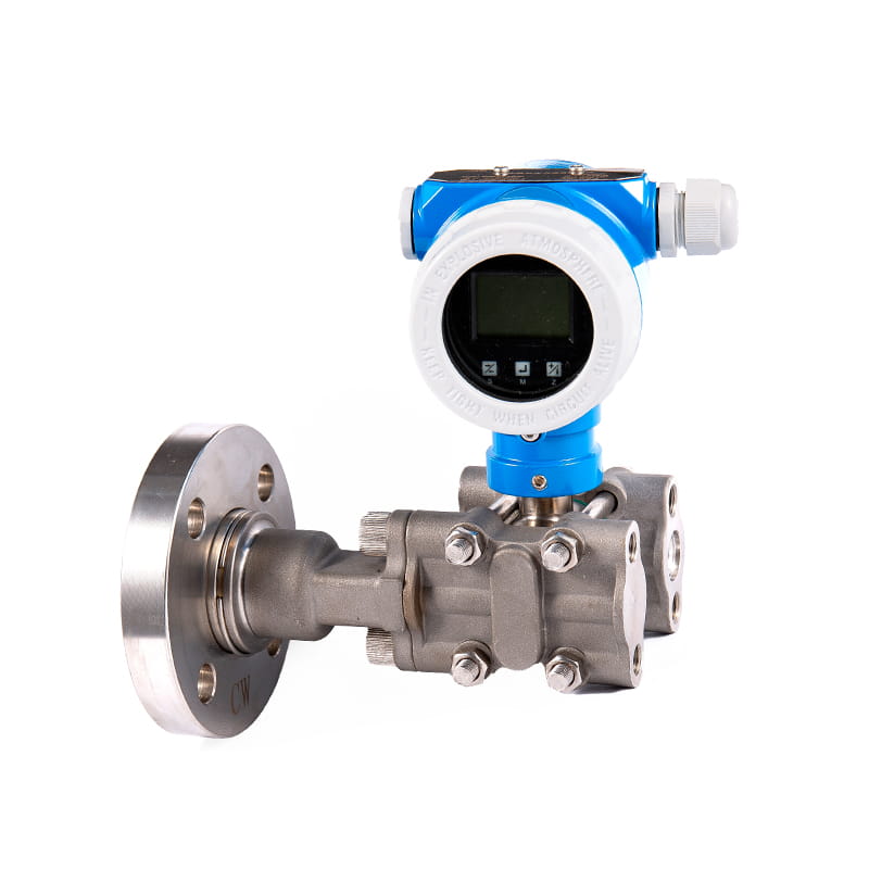
Remote seal (also called diaphragm seal) assemblies are used when the process media is incompatible with the transmitter's internals, or when the process is at very high or very low temperatures. The remote seal consists of a flexible diaphragm mounted directly to the process connection, filled with a capillary fluid (such as silicone or food-grade oil) that transmits pressure to the transmitter without exposing the sensing element to the media.
Applications requiring remote seals include highly viscous fluids, slurries, crystallizing media, corrosive chemicals, hygienic (sanitary) processes in food and pharma, and cryogenic or high-temperature services. While remote seals add response lag and introduce temperature-related fill fluid errors, the protection they provide makes them indispensable in these demanding environments.
A structured maintenance program significantly extends transmitter service life and protects calibration integrity. Key maintenance activities include periodic calibration verification, visual inspection of housing and cable entries for corrosion or damage, flushing of impulse lines to remove sediment or condensate, and checking process connection seals for leakage. For HART-capable transmitters, running periodic diagnostics through a handheld communicator or asset management software can reveal developing faults before they cause failures. Keeping spare units on hand for critical measurement points is also a recommended practice in high-availability facilities.

◆ Model:YE60 YE100 YE150 ◆ Use: Membrane box pressure gauge is also called micro pressure gauge....
See Details
◆ Model:YEB60 YEB100 YEB150◆ Use: This series of instruments are suitable for measuring the low micr...
See Details
◆ Model: YLm60 YLm100 YLm150◆ Application: This series of instruments are special instruments for de...
See Details
◆ Model: YC40 YC50 YC60 YC75 YC100 YC150◆ Use: This series of instruments are suitable for measuring...
See Details
◆ Model: YJY100 YJY150◆ Use: Absolute pressure refers to the pressure which is higher than absolute ...
See Details
◆ Model: Y¨-ML Y¨-MF Y¨-MG Y¨-MZ Y¨-MK Y¨-MN Y¨-MS◆ Application: Due to the indirect measurement str...
See Details
◆ Model: YTT100 YTT100A YTT150 YTT150A ◆ Application: This type of instrument is suitable for measur...
See Details
The gas monitoring alarm system is designed for optimal safety and usability. It features a user-fri...
See Details
The Temperature sensor WZPK is renowned for its long service life and exceptional stability, making ...
See Details
The Float level gauge UHB is engineered for high-precision measurement, providing accurate and relia...
See Details


